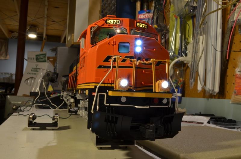
30-20062-3.jpg rkcsx

 30-20062-3

This engine had one #board out(pinched wire and now fixed)but i decided to take some voltage readings. With the # board lamps  2 pin 4 wire molex disconnected a reading at the board read -23.3 vdc.

My question is this some sort of pulse width supply and if so how does it work?

Attachments

Images (1)
  • 30-20062-3.jpg rkcsx
Last edited by willygee
Original Post

Replies sorted oldest to newest

I have used 150 when powering a series marker set off Bulb circuit and 300ohms when a single LED.


The 6V are out there, believe they are made for older autos and boats with 6V batteries.  I have seen them. 


You need to be careful when taking measurements on PS engines.  AC is not common, though you can get away with it when measuring purple +.  Blue is typically PCB Ground.  Purple is DC positive.  The colored wires are return to PCB ground via FET for PS-2.  G

Last edited by GGG

I'm sure a 6V item exists, I just never needed or wanted one.  I do wonder if a boat item would fit where they need to go in the locomotive.


Technically, for a white LED, you can use 150 ohms, as it's operating voltage is 3V at 20ma.  I don't like to push them to the limit however, and the difference in light output is minimal between 150 and 220.


I just mimic the resistors that MTH used in older CV boards. I said 150 for series markers which are 2 red or green in series.  I use 300 for the single LED.  I change parallel markers to series for PS-2 use.


The LED are small for indicators.  I think that is what they are used for, not lighting the cabin or engine compartment

I don't worry about them blowing the bulbs, I just like the look of headlights with the focused beam of LED's.  They just look a lot more like real headlights to me.  Other than really ancient steamers that had really weak headlights, looking down the track into the headlight of a locomotive you'll see a very bright light.  IMO, the LED's look much closer to what the prototype looks like.  Obviously, the color temperature is all important, I have several shades of warm white 3mm and 5mm LED's, as well as the bright white.


 I played with several LEDs in my G scale upgrades before I got it perfect for me. I used super bright warm white bulbs with the smallest resistor I dared (180? I think). When the trains are outside at night, they actually look real (scale sized of course). They are tough to look straight into because they're so bright.

 I think they are not really focused and won't look quite like real, but they are darned close now. I didn't like the stock bluish ones that came with the engines (lower photo).

DSC_0020 [800x530).jpg

  DSC_0266 [800x530).jpgThe nice thing about using LEDs is you can add extras. I put ground lights on the PS2 interior light circuit that look cool to me. I had hoped that the new PS3 MTH G scale releases would start coming with more lighting effects. The MTH O scale Dreyfus I got has some cool lighting.


Originally Posted by GGG:

I just mimic the resistors that MTH used in older CV boards. I said 150 for series markers which are 2 red or green in series.  I use 300 for the single LED.  I change parallel markers to series for PS-2 use.


The LED are small for indicators.  I think that is what they are used for, not lighting the cabin or engine compartment

In replacing the 2 filament number board lights is there enough forward voltage to wire in 2 warm white led's[3.3 forward voltage] in series?

Add Reply

Post
The DCS Forum is sponsored by
×
×
×
×
Link copied to your clipboard.
×
×