
You can change the tach tape to a custom tape to change the chuff rate. Note that it will also change the scale MPH calibration, but I doubt that's accurate since this is a different brand locomotive, so that's not a big deal.  If you're getting too many chuffs/rev, reduce the number of stripes on the flywheel, and it'll change the chuff rate.  If it were exactly double the proper number, then you'd want half as many stripes on the flywheel.

A simple way to reduce the number of stripes by half is to simply use a Sharpie marker and color in every other white stripe.

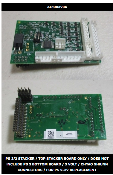
MTH sells the top board alone for $31, and they show it in stock.  I recently bought several of them.  You might guess I'm somewhat of a stickler for things working properly, so it would bug me that the headlight didn't work as intended.

Again, awesome info!

I appreciate the "work arounds" offered, but I'm OCD enough that it not working quite like it should, especially because of my mistake, would annoy me to no end, so I ordered the top board. It's more or less a deal where I gently pry up and unplug the top board, and then reverse the process for the replacement, correct? No need to reprogram anything?

That's interesting about the tach stripe. I'll get out a sharpie this week and update on how that goes, lol. Still learning a lot... I didn't even know that it was the black/white color difference that triggered it; I thought maybe there was something magnetic about parts of the strip that it read off of, kind of like an ABS reluctor ring on a car or something.

@Mallet1218 posted:

Again, awesome info!

I appreciate the "work arounds" offered, but I'm OCD enough that it not working quite like it should, especially because of my mistake, would annoy me to no end, so I ordered the top board. It's more or less a deal where I gently pry up and unplug the top board, and then reverse the process for the replacement, correct? No need to reprogram anything?

That's interesting about the tach stripe. I'll get out a sharpie this week and update on how that goes, lol. Still learning a lot... I didn't even know that it was the black/white color difference that triggered it; I thought maybe there was something magnetic about parts of the strip that it read off of, kind of like an ABS reluctor ring on a car or something.

Correct, just remove the top board, wiggle it a bit and work it out, the 40-pin connector is pretty delicate.  Pop the new one on and make sure it's seated fully, put it back in the holder.  No programming required.

The tach sensor is just an optical sensor, I regularly print tach tapes using half-page gummed shipping labels.   We're low tech here in the model train department.

@GGG posted:

I would complete the installation before making the swap.  Make sure you have all the hiccups resolved.  No need to damage another board right?  This is your first rodeo.  G

Sage advice, sir, and carefully noted. I'm actually in the process of doing that exact thing. Built my harness with all of my accessory lights last night and tested it by itself at 5.5 volts with a DC train controller I had on hand. Before I connect it within the locomotive, I'm going to try the engine out with a regular MTH headlight bulb once I have the new board just to make sure all functions well in "standard form."

Once the above is done, I'll finally hook up my light setup. *Should* be fine, but at least I'll know the source of the issue if things suddenly go south after hooking up my finalized wiring.

On a side note, should it matter if I'm wiring my headlight, marker lights, firebox, and cab light LEDs off the 6v headlight lead in series vs parallel? I was trying a couple of different resistors to vary brightness, in particular on the marker lights, and it seemed to light better with a parallel setup and individual resistor for each light. My logic says a parallel wiring setup should be fine, but again, I figure it doesn't hurt to ask before I eventually hook it up and potentially fry another board. I see that MTH marker light harnesses come already wired for series, and I'm not sure if that's out of necessity or preference on their part.

Last edited by Mallet1218

PS-2/3 markers are wired in series, but for PS-3 LED are parallel even on a double harness.  Since you are trying to run all the LED off one source and you have White and Marker LED merged you might have an issue.  I would parallel them, but I would have the markers LEDs in series with each other and then in parallel with the white LEDs; and you will have to select resistors to get it to work.  G

Last edited by GGG

Well, I wanted to keep this thread alive until I finished the job, and it seems I’ve finally crossed the finish line! Got the new top board today, switched them out, and the headlight worked fine. Then moved on to installing the led harness I put together, worked on wire management (things are TIGHT in the front because of the smoke unit, light wiring, and forward facing flywheel), crossed my fingers, and fired it up!

I did the aforementioned mod with a sharpie on the tach tape, and it worked perfectly!

I’ve gotta say, I’m extremely pleased with the outcome, and I really, really appreciate all the help and advice offered here. Y’all are awesome. Felt good to finally, and confidentially, slap that “PS3 Upgraded” sticker under the tender, lol.IMG_3414

Attachments

Images (5)
  • IMG_3409
  • IMG_3410
  • IMG_3413
  • IMG_3412
  • IMG_3414
@Mallet1218 posted:

I’ve gotta say, I’m extremely pleased with the outcome, and I really, really appreciate all the help and advice offered here. Y’all are awesome. Felt good to finally, and confidentially, slap that “PS3 Upgraded” sticker under the tender, lol.

I'll bet you feel like you were wrestling alligators for this one.   Great to hear you crossed the finish line, they get easier every one you do.

Add Reply

Post
The DCS Forum is sponsored by

OGR Publishing, Inc., 1310 Eastside Centre Ct, Ste 6, Mountain Home, AR 72653
800-980-OGRR (6477)
www.ogaugerr.com

×
×
×
×
Link copied to your clipboard.
×
×