 I am new to wiring a layout and wanted suggestions to how many points should I wire my layout. I have enclosed a SCARM file of my layout. I am using MTH Realtrax and would like to know how many lockons would I need for this layout.
Replies sorted oldest to newest
IMO for best performance you should have a power feed about every 8 to 10 track joints, irrespective of how long the track pieces are. Especially if you are running conventional, so as to avoid slow downs in the corners, which is very annoying. With command operation you don't get this problem. The track joints are where you will get the most discontinuity and therefore power loss. If you are wiring for dcs the recomendation is every 12 track joint maximum, I believe.
In the end regardless of what you choose, you can always add more feeders if you have any bad areas. ![]()
Rod
Thanks Rod. The plan is to go DCS. So I'll try the every 12
Not sure how it works out with the joint minimums, but I'd probably start here and see if it works out. Like was said, you can always add more.
Attachments
Richie's suggested power feeds look pretty good.
Another thing you probably have read is the recommendation for DCS to insulate the center rails between power feeds, thus making a bunch of isolated blocks. While well-intentioned, this really does not work well with most modern track systems like Realtrax and Fastrack. It works pretty well with old-school tubular, as long as you do it when laying the track, not later. My layout was built well before DCS, so they blocks are not insulated, and it all works quite well anyway. Also I did not star wire, and there are 2 or 3 track feeds from each power wire run, which is another DCS no-no. But as a wise man once said, hey go ahead and give it a try, you have nothing to lose. ![]()
Rod
Assuming you mean to connect the transformer outputs to the red and black inputs and then pairs from each port to the track/lockons, then yep !
As a bonus, if you mount it in a centralized location, you've now star-wired your layout.
If you're running command with a fixed output voltage you can also use the spare ports to power any accessories that use that voltage.
@tlcottone posted:
That's the perfect thing for DCS star wiring.
And a further bonus to what Richie mentioned is you can put a TVS right across between the red and black input connectors at the near end of that terminal block. Easy-peasy! ![]() You can (almost) never have too many TVS's.
You can (almost) never have too many TVS's.
Rod
What exactly is a TVS ?
@yardtrain posted:What exactly is a TVS ?
I think he meant TIU
@Rod Stewart posted:That's the perfect thing for DCS star wiring.
And a further bonus to what Richie mentioned is you can put a TVS right across between the red and black input connectors at the near end of that terminal block. Easy-peasy!
You can (almost) never have too many TVS's.
Rod
What exactly is a TVS ?
TVS Transient Voltage Suppressor. Designed to reduce Printed Circuit Board damage from voltage spikes. I always thought most of them were, one and done. Foggy head says, maybe not.
TIU Track Interface Unit. Designed to supply track power, with the RF (Radio Frequency) signal(s), that does/do all those magic push button functions. Two Part device, there is a handheld remote also. MTH product comes as a kit.
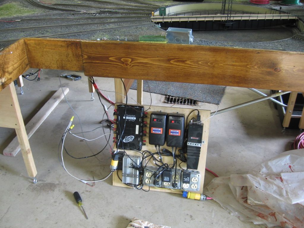
TIU pictured upper left of this power board.

Transient voltage suppressor (TVS) is discussed in numerous other threads on this forum. Great electrical protection for expensive command control engines and accessories.
Chuck
Here’s a link to a thread here in the electrical forum that explains the “Transient Voltage Suppressor” electrical-reference-materials-andamp-manuals also a screen shot of the thread on TVS.


