The LM2596 based modules will handle far more current than the LM317 based modules.  They are two totally different types of power conversion.  The efficiency of the LM2596 based modules will be in the 85-90% range.  The efficiency of the LM317 based module varies based on the input voltage, but it'll be MUCH lower, sometimes down in the 20% range.


All the input power that isn't delivered to the load is dissipated as heat, which is sometimes a major issue.


I have some LM317 based modules, with any significant current draw through them, the heatsink gets pistol hot!  I've used the small LM2596 modules to supply 1/2A to a smoke unit, it's still barely above room temperature.


Take the ratings that you see in the eBay ads with a grain of salt, they are stated under ideal conditions.  The 1A for the LM317 modules is with a minimal input/output voltage differential to minimize the power dissipation, in the real world, that rarely happens.


Originally Posted by repair technician:

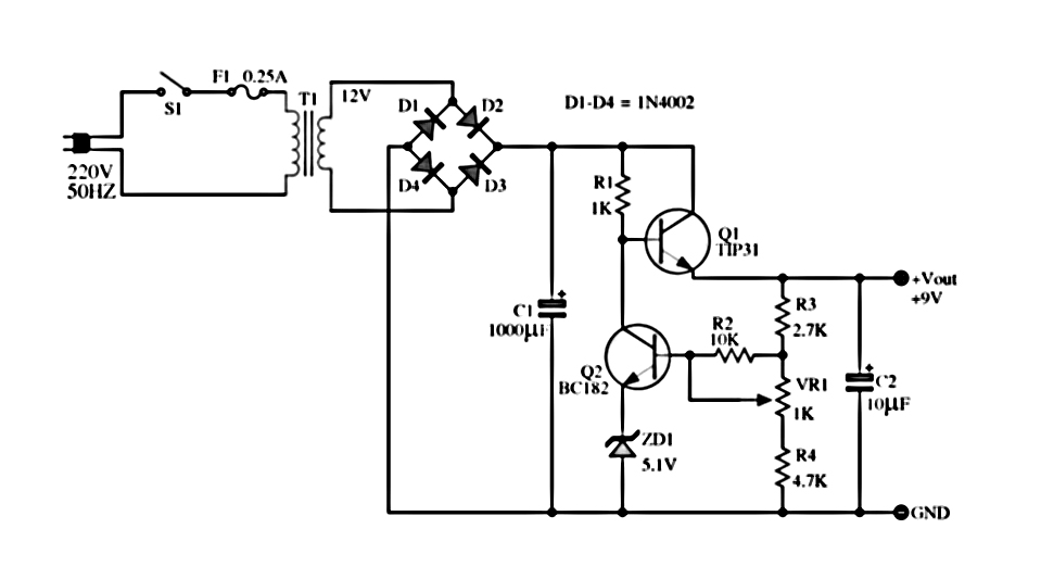
here is one try this! the only similar one would be buy a 3 volt transistor regulator and then run the ac from the track rail into a full wave bridge rectifier and the output of the full wave rectifier would feed in to the 3 leg transistor regulator.

let me know which one you like and ill give you a parts breakdown list

Alanhttp://www.next.gr/uploads/4/6%2B-%2B12%2BVolt%2BPower%2Bsupply.jpg

Hi Alan

I would like to try this as a learning project.  Could you send me a larger schismatic and a parts list or part numbers?  I probably will order thru Digi-Key.  My input is probably a old 1033 that I have somewhere. E-mail in profile or tthompson3@sc.rr.com.

Thanks

Tommy


Originally Posted by thebeeman:
 

I would like to try this as a learning project.  Could you send me a larger schismatic and a parts list or part numbers?  I probably will order thru Digi-Key.  My input is probably a old 1033 that I have somewhere. E-mail in profile or tthompson3@sc.rr.com.

Thanks

Tommy


As a learning project consider building this circuit using an LM317 instead. The LM317 essentially replaces the two transistors and Zener diode in the "discrete parts" circuit you are looking at, and throws in a few other features at the same time. Schematics and parts lists for a power supply using the LM317 are readily available with an internet search. As others have pointed out, a regulated power supply built this way will dissipate a fair bit of heat going by converting 18VAC to 3VDC, so the LM317 (or Q1 in the discrete parts diagram) will need a heat sink.

Last edited by hmb

That's way more complicated than it needs to be to address your requirements, not to mention it's got a transformer and runs of 230VAC!  Here's one that will probably be a lot simpler to build and has adjustable output to anything you desire.  You can substitute a fixed resistor for R1 if you want a single voltage, common values included.


LM317 Voltage Regulator from Track Power

Attachments

Images (1)
  • LM317 Voltage Regulator from Track Power

OK Gunner, Pls stay with me on this one. I like the schematic and it will good learning tool.  But, however I have a couple of questions.

Is your DF005 B1 a premade module or 4 single diodes? If diodes, what number?

Is your R1 a pot?  If so, what range?

Is your C2 a .1 or 1 uf cap?  Could not see clearly.

Last but not least, but just as important, I just ain't too bright upstairs therefore I could not get the formula Vdc output = 1.25V(1+(R2/R1)) to calculate to a correct output Vdc. I'm missing something but can't figure it out.  Can you run some hard numbers in the formula?

Thanks Gunner, All of you guys on the forum have helped me along the way.

Tommy 


DF005 is a bridge rectifier, just put it in Google.

R1 is a 2500 ohm pot, though it could be one of those fixed resistors that I calculated for you.  That's the string of voltages below the formula.


C1 is a .1, though it can be most any larger value.  It's primary purpose is to prevent instability of the regulator under certain loading conditions.


Here's all you ever wanted to know about calculating the resistor values.


LM317 Calculator and Info Page


I posted that link by mistake for those "kits"... I wouldn't buy a kit, because as you say, you can buy the components from DigiKey. I copied and pasted the wrong link. I want ready to use stuff, not electrical component kits. My goal is buy it, use it when it comes to that kind of stuff. Not buy it, build it, use it. I have enough stuff to build with the layout Sorry for the bad link. 

On the other side of wanting ready-to-go items, a lot of people here want to learn more about electronics (that includes me) and soldering and etc. These kits would be great projects for those wanting some experience in that department. Something you can learn with and use after it is completed. And as others have said, you just can't beat the prices!


Hmmm...guess I should get a couple.

Last edited by rtr12

Add Reply

Post
×
×
×
×
Link copied to your clipboard.
×
×