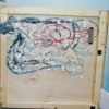
Live Touch Track Diagram Control Panel Construction and Layout Wiring Part 1 of 2
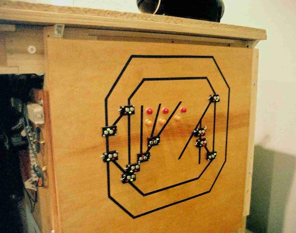
The Live touch track diagram control panel allows identification and control of the uncoupling track sections, track switches and track sections by the mini control panel switches.
It was decided to make a control panel with a Live Touch Track Diagram when I built my operating, switching 027 layout with total 31 Marx 1590 switches (on two control panels), starting in 1976 or forty year plus year ago.
Model Railroading book shows an active track diagram control panel with 7 toggle switches located on the diagram. Most Lionel train show room layouts had a track diagram but the switch control switches were not on the diagram and their layouts mostly consisted of 5 or 6 isolated loops with only a few sidings. The book Greenberg's "Model Railroading with Lionel Trains", Vol 11 of 1992, page 40, shows a control panel with 38 Lionel switch controllers lined up and sheet with the track plan below. I do not know how they identify which Lionel switch controllers operates which track switch.
I have had extensive experience, from 1965 to 2010 or so, with flow chart diagrams control panels in several chemical and refinery plant control rooms. These control panels were often from knee high to ceiling and grouped by function with 10 to 15 feet of width each. They had instruments to control flows, temperature, pressure, etc for various spots in the units they controlled. These instruments were located on taped or marked out flow sheet on the panel that diagrammed the process flow and made it possible to easily show and control the process. I saw it was easy to follow flow diagrams and one would work with a model train track plan diagram . It was made with mini push button switches and slide switches located showing where the Marx switches, un-coupling track sections and the sections of track blocks were actually on the train layout. (note: now days these industrial plants have computer controls and process diagrams on computer monitors, some having active touch screens for control).
It was important to keep the control panel easy to operate, quick to operate and logical. Having 20 switch controllers lined up would make it impossible to find the controller of the switch I wanted to throw quickly and easily.
The first reason live touch track diagram control panel was picked is I have 20 Marx 1590 track switches on the main train board and having that many switch controllers lined up would be difficult to operate deciding which control switch went with which track switch. The live touch track plan diagram makes it easy to find the proper switch. The un-couplers require an additional 14 push button switches to be matched with the un-coupler track section and would be hard to identify which switch worked which un-coupler track section. An active touch track diagram control panel solves both these problems.
A second reason is it saves space by combining the switches for the track switches and un-couplers and on the small track diagram. This is possible by using Radio Shack momentary mini push button control switches which are located at the spot on the diagram where the track switch or uncoupler track is located on the train board.
A third reason is the track diagram shows a picture of the layout and helps view hidden parts of the layout and I like the looks of an actionable touch track diagram as it is less cluttered than a large bank of Lionel switch controllers and seeing the track plan helps identify the different tracks on the layout. The track diagram helps visitors see where all the tracks are going. Lionel used track diagrams to show a picture of the track plan on some of their showroom layouts but they did not have active switches on the track diagram to control the layout.
There is Still a Need for a Live Touch Track Diagram for modern Train Control Systems
The Live Touch Track Diagram developed is a 1940-50's version of a Touch Screen laptop computer. Many modern model train operators, that use DCS and DCC, walk around with remote controllers and have a layout with 20 or 30 switches, will have the same issues I would have if I just lined up 20 Lionel switch controllers. Many modern train layouts operate at slower scale speeds giving them more time to operate the switches. The use of a small Live Touch Track Diagram control panel like mine, will make identifying the switches to be activated, for a given route of the train, easy and quick. So this type of mini track push button switches on a track diagram still make operation of modern DCS or DSS controlled layout easier, quicker and more accurate (less switch throwing mistakes).
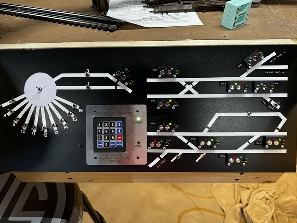
Note on main control panel live touch layout track diagram Shown Below: The RED and GREEN Mini Push Button switches are for track switches. The two YELLOW mini push button switches direct the train to the hidden track section behind the background. The BLUE push button switches are for uncoupling track sections. The BLACK slide switches are for cutting on and off power the track section they are on. When switch slide WHITE shows completing the white of the diagram, the power is ON. When the switch slide shows BLACK when the switch slide lever is blocking the white track of the diagram,the power is OFF.
The control panel frame was made from ¾ boards and glued and screwed to side of the train board. The center section is for the track diagram. The sections on the side of the track diagram are for other slide switches for accessories, building lights, etc. A section to the right and one to the left are for two Lionel LW transformers.
A second newer Live Touch Track Diagram Control Panel is on the New Train Board shown below, with the third Lionel LW transformer and an HO transformer for the back and forth street car trolley. The two control panels are located about 3 feet apart forming an L and can both be reached by one operator and can accommodate two or three operators.
The live control touch track diagram panel is made from 1/8 inch tempered Masonite. It was painted medium gray. A 1/8 inch groove was sawed in side board of the layout where the control panel is to be, above the angled side boards of the control panel. This groove accepts about a 1/4 inch of the 1/8 inch Masonite panel with the diagram and will anchor it on the top. The Masonite panel is just slid along the control panel side boards and into the groove in the side board of the layout. Three small 1/2 inch counter sink headed screws are used to hold the bottom of the Masonite diagram control panel to the front edge of the control panel frame. The removal of these three screws will allow the 1/8 inch Masonite control panel diagram to be slide back a 1/2 inch and then pushed up the bottom exposing the inside of the control panel for maintenance or expanding the control panel. See picture below of opened up control panel.
Part 2 coming soon
Charlie


