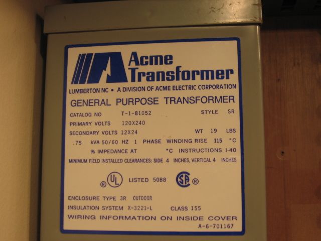
Any recommendations for transformers (or "bricks") that any of you prefer to power accessories, as I plan to have a dedicated transformer for running the accessories on my layout?

A key question is the following: Are modern circuit breakers required for accessories, or, are such modern circuit breakers generally required for equipment with chips and circuit boards, like modern locomotives?  On a companion point, there is a suggestion in another thread that the Postwar ZW may be inappropriate, or, less appropriate, because of the style of windings, and the resulting "shared" power.  Since I still have my original ZW purchased by my father in 1961, and, it has been reconditioned, that would be my first choice.

The referenced accessories would include the typical postwar style lighting accessories such as lamp posts, rotary beacons, floodlight towers, and lighted billboards, etc.  Additionally, I plan to wire a number of operating accessories, including a Bosco operating (milk) car, icing station, coal loader, barrel loader, lumber loader, etc.

As always, thanks for the assistance!

Last edited by Dennis GS-4 N & W No. 611
Original Post

Replies sorted oldest to newest

Dennis,

I use an old Lionel Z Transformer with 4 adjustable outputs. As you probably know each accessory works best with a certain Voltage!  I pretest each one to see what voltage it works best at !!  Then put a small sticker on it with that voltage written on it. Then when I add it to my Layout I adjust the output of one the Z control knobs to that Voltage! Then as I add Accessories I adjust each of the outputs to match the voltage required for that accessory! When I have preset each of the Four Outputs to match the Accessories, I mark the Knobs w/a small piece of tape.  If I add an accessory , & don’t have that specific Voltage preset on the “Z”, I connect it to the closest one!  The Lionel “Z” Transformers can be found  , very reasonably, at most Train Shows! Great Transformer for Accessories & they are rated at 250 Watts .

Fredstrains posted:

Dennis,

I use an old Lionel Z Transformer with 4 adjustable outputs. As you probably know each accessory works best with a certain Voltage!  I pretest each one to see what voltage it works best at !!  Then put a small sticker on it with that voltage written on it. Then when I add it to my Layout I adjust the output of one the Z control knobs to that Voltage! Then as I add Accessories I adjust each of the outputs to match the voltage required for that accessory! When I have preset each of the Four Outputs to match the Accessories, I mark the Knobs w/a small piece of tape.  If I add an accessory , & don’t have that specific Voltage preset on the “Z”, I connect it to the closest one!  The Lionel “Z” Transformers can be found  , very reasonably, at most Train Shows! Great Transformer for Accessories & they are rated at 250 Watts .

Thanks Fredstrains, that is very helpful!  I will actually adopt many of the strategies that you suggest for recording "best" accessory voltages.  I have a ZWL, to power the layout, and have run a dedicated accessory line across the layout tables hoping to get away with one "bus" line.   As I suspected, trying to power my switch tracks, run rotary beacons, and, lights from the same voltage post was likely destined for failure.

I also have my original postwar ZW which was reconditioned, so I can use that as you suggest.  With respect to the operating accessories, I was hoping to wire them all to one dedicated power bus wire attached to one of the variable voltage posts on the ZW.  Your excellent system will then be adopted for marking the best voltage(s) for each accessory.  I was then planning to run one accessory at a time with the properly adjusted voltage(s), and push buttons or sliding on-off switches to activate them.  To me, this system would be somewhat similar to the light switches at home which are always wired, but not powered until switched on.  Then the power to each accessory would be delivered on demand at the proper voltage.   Any thoughts or suggestions?

cjack posted:

The new ZW-L, and the newest Powerhouse bricks (18 VAC) have the best (fast) protection. The PSX-AC

https://dccspecialties.com/products/psx_ac.htm

is the best add on for other older ZWs or the like. You can also get them from Charles Ro train store.

Thanks Chuck!

Might you be aware of any postwar accessories that would require a fast-acting circuit breaker?  In this regard, I power my layout with a ZWL, but have already dedicated three of the voltage posts for mainlines. The fourth is used to directly power my switch tracks when I am running conventional locos.  

I can use my reconditioned ZW for accessories, including operating accessories.  To my knowledge, none of these accessories have circuit boards, or friable chips.  I would think that I could just use the ZW for this purpose without fast acting circuit breakers.  Any thoughts?

Thanks! 

Last edited by Dennis GS-4 N & W No. 611
shorling posted:

I use  plain old step down transformers you can purchase from an electronic distributor like Allied or Newark.  110 V primary, 28 V CT secondary provides two 14 volt outputs.  The transformers come in various sizes to suit you current requirements. 

Thanks Steve,

Electrical and electronics terminology is frequently still a bit foreign to me, notwithstanding my college physic courses!  ( I did master: "Watts = (Amps) X (Volts)" -- assuming I remembered that correctly!

My follow-up research to your post indicates:

"A current transformer (CT) is type of transformer that is used to measure alternating current (AC).  It produces a current in its secondary which is proportional to the current in its primary."

Does that mean that  the transformer you described can produce 110V in one output, and, 14V in two other outputs?

Are the voltages fixed at 110V, and 14V, or are the voltages variable? 

Last edited by Dennis GS-4 N & W No. 611

I believe that what shorling was talking about is a 28 volt secondary coil with a Center Tap (CT). Where the tap is placed on the secondary coil determines the voltage obtained at that position.

It has to do with the number of windings on the secondary coil. Using all the windings yields 28 volts. Using half the windings (Center Tap) yields half as much.

A step down transformer will "step down" your household 110 VAC input to 28 VAC output with a  center tap secondary.  The secondary output will have 3 wire lets say 1,2,3.  Lets say wire 2 is the center tap. Voltage between wires 1 and 3 will be 28 VAC.  Voltage between 1 and 2 or 2 and 3 will be 14 VAC each.  If the transformers 28 VAC output is rated at 4 amps then each 14 VAC output can supply 4 amps for a total of 8 amps @ 14 VAC.  The outputs are fixed, not variable.  Watts as you quoted = 4 amps x 28 volts = 8 amps x 14 volts

Last edited by shorling
Consolidated Leo posted:

I believe that what shorling was talking about is a 28 volt secondary coil with a Center Tap (CT). Where the tap is placed on the secondary coil determines the voltage obtained at that position.

It has to do with the number of windings on the secondary coil. Using all the windings yields 28 volts. Using half the windings (Center Tap) yields half as much.

Thanks Leo and Steve!

The terminology of "Center Tap" was not familiar to me, and I honestly still don't know if such a "Center Tap" is directly connected to a binding post.  After reading the posts a few times and doing some internet researches, I have a little better understanding of how the throttles on a ZW "vary" voltage.  I presume that the rotating throttles actually "tap" the transformer coil at different places, with each "variable "tap" yielding a different voltage.

Last edited by Dennis GS-4 N & W No. 611

That's correct. The variable voltage from the transformer comes from the "rollers" that are the "taps" across the secondary coil.

But that's only for the old school Post War and earlier transformers like the 1033, ZW, and others. Modern transformers use electronics to vary the voltage usually with "triacs" which are high yield power transistors.

Nice job on your research!

Thanks Leo,

I really appreciate the explanation!  

It's always enjoyable to learn how items such as a Postwar ZW actually work. The ZW is clearly a "black box" that I would not feel comfortable disassembling and repairing, and I leave such repairs to people with more specialized training. The information is also helpful for better understanding "step-down" transformers, and how to more effectively take advantage of their utility for model railroaders like us.

Our local hobby shop that repaired my "first year model" Celebration Series ZW has, unfortunately closed.  That source was always great for getting answers to technical electro-mechanical, and, layout power source questions.  The owner was often kind enough to bring me into his "Back Shop" to show me how he was doing different repairs.  I should have watched the ZW repair!

Last edited by Dennis GS-4 N & W No. 611

Generalized, a transformer is nothing more than two bunches (i.e. coils) of enameled wire wrapped around a core.  The wire insulation is an enamel coating like paint.  So for illustrative purposes lets envision a pretend secondary 10 VAC winding consisting of 10 turns of enameled wire wrapped around a square core.  Now sand off the enamel on one side of the square exposing the copper wire.  The 10 VAC secondary has two wires, one at each end of the wrapped core that looks like a coil.  If you measure the voltage across the two wires, lets call them A and B it will be 10 VAC.  Now number each turn from 1 to 10.   If you measure the voltage been A and the exposed copper of turn 1, it will measure 1 VAC.  Measure been A and turn 2 will be 2 VAC and so on.  If you measure at the center of the turns, that's where the "center tap" would be.  Just a wire connected to the center of the turns.  Measurement from either A or B to the CT will be 5 VAC.  Now, scrape your meter probe across the all the exposed copper winding's and notice the meter goes from 1 to 10  VAC as you pass each successive winding.  The variable transformer works just like scraping your probe across the winding's only envision your probe tip with a conductive roller or brush made out of a conductive material like carbon.

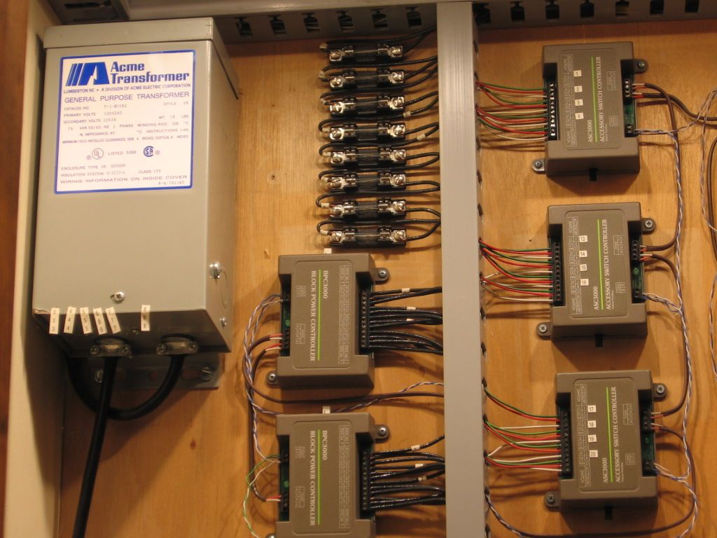
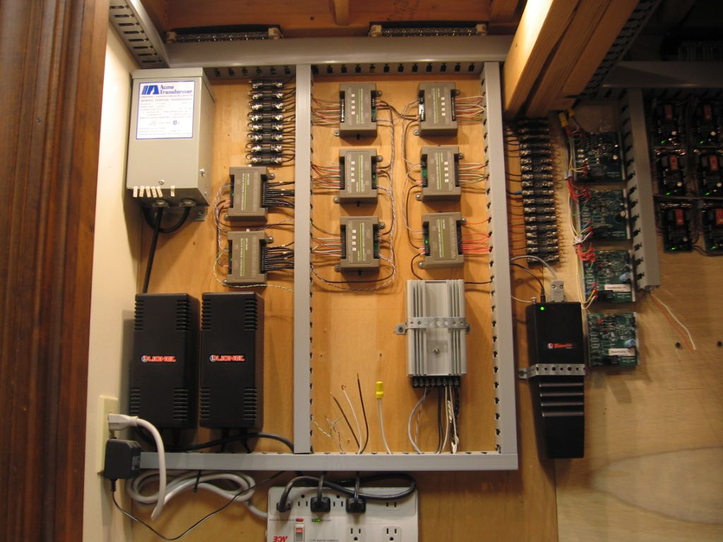
I want to thank Dennis for adding this topic since I have not wired my accessories yet, and have learned that a common voltage might not be the best approach.  I want to comment on the wonderful tidy wiring that Mike had done with his Legacy control boxes, and I also have yet to do.

When I noticed the comment on the Current Transformer it induced me (pun intended) to brush up on what a Current Transformer is and how it differs from a standard voltage transformer.  Of course all transformers transform both current and voltage from primary to secondary and vice versa keeping the input/output power essentially the same except for the efficiency factors.  But I asked myself " What is this Current Transformer all about"

So as the this thread mentions the Current Transformer is for measuring applications.  I knew The transformer itself doesn't measure, it steps currents and voltages up or down accordingly, so what was this all about.  

Current transformers are transformers wired in a specific way to perform measurements, typically with an ammeter in parallel with the secondary and the primary in series with the load and the secondary across the measure device (ammeter).

It is important to keep the ammeter connected otherwise the secondary will act in its normal way and produce a very high voltage,  I have pasted a more detailed explanation below.


Even though I sell ZWLs and have one, I think purchasing one just for accessories alone is expensive overkill and somewhat of a waste of the features for rail operation such as the nonlinear output voltage waveform, and the ability to program an output as an engine controlled from a remote etc ....  Of course if you are using a ZWL in conjunction with track operation, as I am it is a good choice.


 Current Transformer, (CT) is a type of instrument transformer used to convert a primary current into a secondary current through a magnetic medium. Its secondary winding then provides a much reduced current which can be used for detecting overcurrent, undercurrent, peak current, or average current conditions.

A current transformers primary coil is always connected in series with the main conductor giving rise to it also being referred to as a series transformer. The nominal secondary current is rated at 1A or 5A for ease of measurement. Construction can be one single primary turn as in Toroidal, Doughnut, or Bar types, or a few wound primary turns, usually for low current ratios.

Current transformers are intended to be used as proportional current devices. Therefore a current transformers secondary winding should never be operated into an open circuit, just as a voltage transformer should never be operated into a short circuit.

Very high voltages will result from open circuiting the secondary circuit of an energized current transformer so their terminals must be short-circuited if the ammeter is to be removed or when a CT is not in use before powering up the system.


Here are some of  the accessories I still need to wire.  Derrick in background, culvert loader/unloader not shown.

I am also trying to decide whether to use DCS or Legacy or both for accessory control.  

accessories 5

accessories 1accessories 2accessories 3accessories 4panel insidepanel


Attachments

Images (7)
  • accessories 1
  • accessories 2
  • accessories 3
  • accessories 4
  • panel inside
  • panel
  • accessories 5

Mike CT,

That wiring and control panel is literally awe inspiring!

Steve, 

Thanks for the very detailed, yet easily understandable explanation, of how a transformer actually works!  That is very helpful, and, I plan to print this thread for future reference. I now have a much better grasp of the inner workings of a transformer and, in particular, how the voltages can be varied either through fixed voltage or variable voltage posts. Additionally, you inspired me to do a little research to determine which material was actually selected for the "core" of the ZW, and stumbled across this link:

       http://retailers.kalmbach.com/...les/108375spread.pdf

Your comprehensive explanation also makes the workings of the step-down transformers other than those manufactured by a model train manufacturer far more understandable.

Mike Brooks,

Thanks for the added, very helpful information!  (Also, Amazon delivered my guitar hooks, which are headed to the train room today. What a great idea -- now when my playlist gets to one of my favorite Elton John songs, I'll likely think of the train store!)

Also, the layout looks great!  Your wiring and control panel  is also very impressive.

Thanks again!


Last edited by Dennis GS-4 N & W No. 611
Dennis GS-4 N & W No. 611 posted:

Mike CT,

That wiring and control panel is literally awe inspiring!

Steve, 

Thanks for the very detailed, yet easily understandable explanation, of how a transformer actually works!  That is very helpful, and, I plan to print this thread for future reference. I now have a much better grasp of the inner workings of a transformer and, in particular, how the voltages can be varied either through fixed voltage or variable voltage posts. Additionally, you inspired me to do a little research to determine which material was actually selected for the "core" of the ZW, and stumbled across this link:

       http://retailers.kalmbach.com/...les/108375spread.pdf

Your comprehensive explanation also makes the workings of the step-down transformers other than those manufactured by a model train manufacturer far more understandable.

Mike Brooks,

Thanks for the added, very helpful information!  (Also, Amazon delivered my guitar hooks, which are headed to the train room today. What a great idea -- now when my playlist gets to one of my favorite Elton John songs, I'll likely think of the train store!)

Also, the layout looks great!  Your wiring and control panel  is also very impressive.

Thanks again!


Unless you are interested in transformer design, I wouldn't worry too much about core material.  Core material influences magnetic coupling, which relates to transformer efficiency and power factor.   The import specs are voltage, amps and watts.  Oh, of course $$$$.

Last edited by shorling
cjack posted:

The new ZW-L, and the newest Powerhouse bricks (18 VAC) have the best (fast) protection. The PSX-AC

https://dccspecialties.com/products/psx_ac.htm

is the best add on for other older ZWs or the like. You can also get them from Charles Ro train store.

So you can use the 18 VAC Powerhouse bricks to power accessories? Everything I've read says to use 14V for them. Will this cause any issues?

Add Reply

Post

OGR Publishing, Inc., 1310 Eastside Centre Ct, Ste 6, Mountain Home, AR 72653
800-980-OGRR (6477)
www.ogaugerr.com

×
×
×
×
Link copied to your clipboard.
×
×