Finished my final design for new around the wall layout and will be laying Atlas track very soon.  I have a double main line with 4 areas for crossovers.  The inside loop branches off to a single reversing loop within a peninsula.  I also have 6 sidings.  Will be using DCS.  My questions  are: 

1) where and how do I isolate one track from another ? 

2) How do I wire and/or isolate the inside loop connecting to the reversing loop in the peninsula ? 

3) When crossing over from one track to another, what rails get the metal track clips and which get the plastic isolated ones ? 

4) Do you need to isolate one track from another at the straight section of the switch or at the curved portion of the switch ? 

5) Same question applies to  the sidings which will have power controlled by toggles.   

Thanks, Mike


Attachments

Images (1)
  • MM V3 10 MTH full
Original Post

Replies sorted oldest to newest

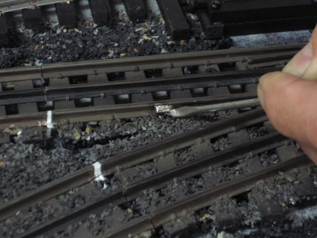
Nice track design,  I am in the laying track down part of our layout.  I too am using Atlas.  For isolating a area Atlas makes a little plastic spacer for the center rail. They are like 4 bucks for a pack of 20 on ebay. Part #6093.  You can isolate your track at any connection weather at a curve or straight spot. We also used a toggle to control our sidings. Power to the center and ground on either outside rail. Hope this helps a little,  I will take a few pics to help. 14529157525079828863841452915866904221524817

Attachments

Images (2)
  • 1452915752507982886384
  • 1452915866904221524817

Forgot to mention too that we control our layout conventionally.  Our first layout was fastrack and I used Lionels Fastrack book for tips on isolating and wiring.  If new to the Hobby I would recommend on getting one. I still use it today. Just my 2 cents, you will get better answers from the experts soon. 

Mike Miller posted:

Finished my final design for new around the wall layout and will be laying Atlas track very soon.  I have a double main line with 4 areas for crossovers.  The inside loop branches off to a single reversing loop within a peninsula.  I also have 6 sidings.  Will be using DCS.  My questions  are: 

1) where and how do I isolate one track from another ? 

That answer is dependent upon two factors

  1. How many transformers you will be using
  2. How many channels of the TIU you plan to use

You can run this layout with one handle of a Z-4000 or a Lionel PH-180 brick and one channel (Fixed 1) of the TIU.  Two would be better.

Then you would have two power districts to isolate and DCS signal blocks within the power districts from Fixed 1 and Fixed 2 of the TIU.

2) How do I wire and/or isolate the inside loop connecting to the reversing loop in the peninsula ? 

Same power district/TIU channel as the red line-any reason that you want to separate it?

3) When crossing over from one track to another, what rails get the metal track clips and which get the plastic isolated ones ?

Only the center rail is isolated if you are crossing from one power district to another and/or one TIU channel to another 

The outside rails should have metal clips everywhere and have feed wires with the exception of an accessory activation area.

4) Do you need to isolate one track from another at the straight section of the switch or at the curved portion of the switch ?

After the turnout 

5) Same question applies to  the sidings which will have power controlled by toggles.

After the turnout, at the beginning of the spur. I only toggle the center rail. The outside rails are always connected. Simple SPST, On/Off type switch   

Thanks, Mike

T8AFAO covered the rest


Mike,

I have two TIU's and two ZW-L's and I am 110% happy with them. I have the four outputs of each ZW-L connected to the four inputs of each of the TIU's. Initially, I had Z-4000, but did not like the lack of regulation. With the ZW-L's, I adjust their outputs to the maximum (about 18.6 v if memory serves me right) and forget about it.

I divided my mains into approximately 20 to 30-foot districts (or blocks) and power each district independently. I have 20 such districts plus 26 sidings and spurs. I used the plastic joiners to isolate the center rails, and the metal (gold and black) joiners for the outer rails. Note than in addition to what Mike CT said above, the outer rails can also be isolated to detect trains in a block; but that is another topic.

One thing to keep in mind is how you plan to turn On/Off the track districts and blocks. You mentioned toggle switches, and that is the way to go; HOWEVER, if you have long runs of wire between the TIU's, the tracks, and the control panel where you intend to mount your toggles switches, you may experience some voltage drops.

Here is what I did:

• I used 12AWG wires from the ZW-L's to the TIU's, and these were 60-ft runs; one around the layout, and the other over the ceiling. I located the TIU's to minimize the wire runs from them to the tracks, so each one serves about half of the layout.

• 14 AWG wires from the TIU's to the eight terminal blocks. These runs were no longer than 20-ft.

• 16 AWG wire from the terminal blocks (actually, relay modules) each of which supplies six tracks, for a total of 48, and these wire runs are between 6-ft and 12-ft.

The relay modules (six or eight relays each) allow the track power wires to be a short as possible since the wires do not go to the toggle switches, and back. I used 22AWG wires from the control panel toggle switches to the relays to turn them, and hence the tracks, On/Off.

I initially used automotive type relays with 12VDC coils, which cost around $5 each. But before I had them all done, I changed to relay modules I bought from e-bay, and like them better. These relay modules require 5VDC for the relay coils, and are pre-wired, include some protection (for the relays) and also have LED's to tell when the relays are On/Off. The ones I bought cost me $10.28, shipped, for a module with eight relays, which is $1.29 per relay!

Anyway, good luck and do not hesitate to ask any other questions. 

Alex

PS. Edited to add:

If you have not already done so, do get Barry's DCS book! I have the pdf version, and really like the ability to search using keywords for the specific topic I need.


Last edited by Ingeniero No1

Mike,

You would have to confirm the logic of this in the DCS forum. Also, I am assuming that you will in command mode only.

If you fire up the ZW-L in conventional mode, with the handles preset to the desired voltage, it would seem that fixed 1 and 2 should be on the mains and the variables on the yard and the trolley. Then you could use the variable to shut down or power up the whole yard by remote and leave the other trolley variable set at fixed with the desired voltage for the trolley. You may want to set them all the same and use switches for the individual spurs in the yard by setting the yard variable channel to fixed.

Four power districts. Using your color coded diagram, black and light blue (except the yard) would be Fixed 1 (and the switches in it), red would be Fixed 2(and the switches in it, possibly the yard throat), Variable 1 the trolley and Variable 2 for yard.

That leaves the need for a switch power transformer and an accessory transformer.

Each power district would be in blocks for DCS wiring recommended practices.

Mike,

I find if you planned your layout on a software program or just sketched it on paper marking the locations on  your plan first then adding the joiners as you assemble the track avoids having to go back and add them later. Mark each one on your plan and check it off as you lay your track down. Identify each one with a number or letter and keep it for reference when you go back and start your wiring. If you have any questions you can reach me at Atlas 908-687-0880 X 7142.

Steve H


Add Reply

Post
The Track Planning and Layout Design Forum is sponsored by

AN OGR FORUM CHARTER SPONSOR

OGR Publishing, Inc., 1310 Eastside Centre Ct, Ste 6, Mountain Home, AR 72653
800-980-OGRR (6477)
www.ogaugerr.com

×
×
×
×
Link copied to your clipboard.
×
×