Hi,
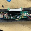
The DCC convention is the blue is common (+12 volts, e.g. rectified track power). White goes to the front headlight and Yellow goes to the rear headlight. The last green one can be used for a beacon or some other lighting function.
You "MAY" need to add inline resistors to the front and rear headlight if they are LEDs and not 12 Volt bulbs (I think Atlas used LEDs on these locos) unless the Atlas motherboard already has resistors for them for these lights, which it may very well have.
A test you can do to see if the board has resistors in place for LEDs is before you connect any of these blue, white, yellow, green wires to the decoder is to start out with connecting just the blue wire to the '+' terminal on a normal AA, C, or D cell battery and then touch the white wire wire to '-' terminal on the battery. See if the front or rear headlight glows at all. If there are resistors on the Atlas motherboard, then the headlight should remain completely dark with only 1.5 volts from the battery (it might be helpful to dim the lights in the room to make sure nothing is glowing). If the headlight glows with just 1.5 volts from the battery, then you will probably need to add a 470 ohm 1/2 watt resistor inline with each of the white and yellow wires. If neither headlight glows then there is a good chance that there are probably resistors already on the board. However, you can test further by hooking up these same two wires to a 9V battery. Hook up the wires the same way, blue to '+' and white to '-' on the 9V battery. If either headlight glows dimly at 9V, then there are resistors on the Atlas motherboard and you can hook them up to the decoder terminal without needing to add any inline resistors. If either headlight flashes very brightly when you momentarily tough the second wire to the battery, then you will need to add resistors since 9V should only make the LED headlights glow dimly if there are resistors on the board. When you do this test the first time with 9V battery, just touch the wires very, very quickly to start, so as to not let the magic smoke out of the LED. LEDs make wonderful fast-acting onetime-use fuses when too much voltage is applied for more than a few seconds. If no additional resistors are needed, then go ahead and hook up to the DCC terminals as I outlined above. The DCC decoder function switches the negative side, e.g. white, yellow, green on and off and the blue is +12 volts all the time that track power is applied. The LEDs will be brighter when hooked up to the decoder since the decoder will be supplying 12V on the blue wire but the resistors on the Atlas motherboard will limit the voltage (actually they are used to limit the current but we'll say voltage since it is easier to understand) to the LED so it does not turn into a flash bulb. Remember, once hooked up to your decoder, you will need to use your DCC controller to turn the front and rear headlight on and off (0 and 1 function, respectively) as they will be off by default.
Scott


