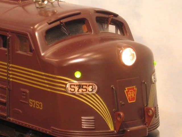
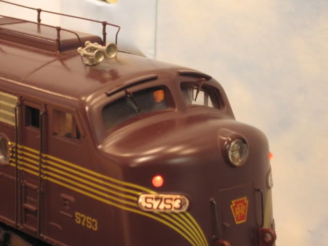
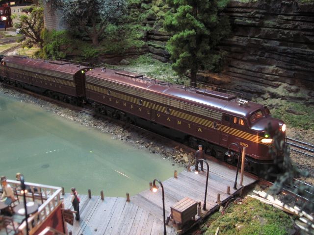
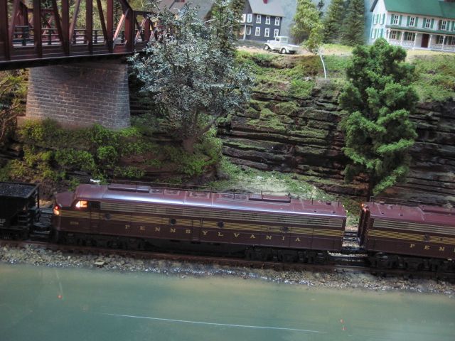
I am working on an Atlas diesel with TMCC/RS.  Uses a Code 08 R2LC.  The headlights are LEDs with only a current limiting resistor.  They are driven in parallel with the Red Marker LEDs.  The red markers are on a PCB with diodes to rectify the input.


The function seems odd.  The front markers go out in reverse, but both headlights stay on.  In neutral all stay on.  What is the actual output of the R2LC light pins, I remember some conversation about reverse half wave switches with each direction change..  Has anyone tried to drive these LEDs with a Constant Voltage input? 


As an update, the above was in conventional.  Testing with TMCC, the headlight comes on with the associated marker off, when you change direction headlight goes out its marker goes on, and the reverse light goes on and the associated reverse markers go off.  So it does seem to be half AC signal coming out.  Turns out the diodes on the Marker PCB are oriented to block the opposite half wave the headlight LEDs gets.  If the headlight was a bulb wouldn't it be on all the time since there always seems to be at least half a sine wave output available? G

Last edited by GGG
Original Post

Replies sorted oldest to newest

LED's on the headlight outputs need a load resistor directly across the headlight output from the triac to reliably fire the triac.  I use a 470 ohm 1/2W resistor as my load.  Without it, I find the headlight operation to be flaky.


The headlight outputs from the C08 R2LC are negative in respect to frame ground, so you have to arrange your LED wiring to reflect this.  I also use a series diode to protect them as I was losing headlight LED's occasionally, doubtless due to some reverse voltage spikes.


I don't really run conventional, but I believe the headlight operation may change and output AC instead of the half-wave DC under command mode.


John, I went back an did some searches and apparently there is a code for the C08 that output a DC signal too.


I was having trouble figuring out the logic of how it was working.  Since polarity matters with LEDs it must be sending a DC signal.  Both the Headlight and the Markers are powered from the same connection jumper in parallel.


The Headlight uses a 1500 ohm resistor.  The Marker PCB uses a 750 ohm and 2 diodes that only allow a single polarity to pass to the LEDs.  In Command when in forward, the headlight goes on, but the polarity that energizes the headlight LED is blocked on the Marker PCB so the red marker LEDs go out.  On the back of the engine the reverse lights go out, but the red marker LED go on.  So even though the reverse light jumper should be deenergized there is a signal passing that energizes the red Markers.


When you go to reverse the opposite occurs.  I wonder if the AC signal is there.  If regular bulbs were in place I assume the AC has to go away other wise the bulb would still light even if it was the negative half of the AC signal.


In conventional I think the AC must be present too.  When you first start the engine in conventional all lights and Markers are on, even though the Headlight and Marker lights need opposite polarity to light.  Interesting scheme to control markers and headlights off the same output triac.  G

I'm having some difficulty in understanding how this is all connected.  Typically, if I want directional markers, I do the following.


Wire the headlight with a series resistor, I normally use a 470 ohm for a single LED, and a 330 if the unit has two headlights.  For the rear markers, they're also connected to the front headlight in series with a higher value resistor, typically I use a 1k resistor.  They're plenty bright, but they don't look like spotlights.


For each lighting output, I put a single diode in the common (+ to ground) return to protect against any reverse voltage.


For both the front and rear light outputs, I put a 470 ohm resistor directly across the headlight outputs from the R2LC to common.


For the rear light, I do the same thing in reverse.  This has worked on a number of lighting updates, I've never seen any odd behavior.


I rarely use the existing boards unless the behavior is easy to understand.  Truthfully, I find in a lot of cases it's more difficult to figure out what the board is doing than to simply replace it with discrete LED's.


One of the sticking points here is probably the fact that the common is really positive, the headlight outputs are negative.


John,  I was trying to understand the voltage applied by the board in stock condition.  Realize this could be wired different.


The headlight and reverse light go to the normal Lionel Mother Board jumper position for lights.  Head light to forward light and reverse light to rear light jumper.  The black wire is common to AC outer Rail and does feed the Red wire lead of the LEDs through a 1500 ohm resistor.  There is not load resistor in the circuit.  The return LED black lead connects to the mother board red wire which is connected to the R2LC pin for lights.


So when in forward the triac output for the headlight must be negative DC and this allows the Headlight LED to light.


The markers are connected to the same wires positions as the headlight.  Forward marker to headlight jumper and rear marker to reverse.


The only difference is the marker has a diode in line that will only allow the Diode to light when the red lead is positive.  A negative voltage on the red lead is blocked from conducting through the Marker LED.


So for the Rear Red Marker to be on when the Headlight is on in forward, means the polarity of the rear triac switched from negative to positive vice off.  Otherwise the rear marker would be off too.


In conventional the markers can stay on in neutral.  So the AC signal must be preset too.  Otherwise it would be impossible for the headlight and corresponding marker to stay on together since they need opposite polarities to operate.  Can't have a positive DC and Negative DC signal on the red wire at the same time.  G

I was pretty sure there was a time that you could have AC on the headlight outputs, which is why I always include a diode.  I had several LED's die after a few months in headlight duty, none after I started using diodes.  I don't run conventional, but I figure it must get the reverse polarity at times for lost signals or other issues like derailments.


In all my measurements and wiring, I assume the headlight outputs are negative in respect to the frame ground, and I've never had an issue with lighting.  However, with all LED's, you do need a load resistor for standard R2LC light outputs.  The ERR stuff adds a load resistor, so it's not needed for ERR TMCC boards.


I'm curious about the markers, you're saying the front markers are connected to the front headlight?  That would light them with the headlight and leave the rear dark, and the same situation for reverse with the front dark.  Maybe I'm still not reading what you're doing here.


Of course, the constant voltage boards for the markers could be a wild card here, without knowing exactly how it's wired, it's hard to say.

John, This is original Atlas wiring.  Yes the Marker PCB has diodes on it, that block the negative signal that lights the head light.  No load resistors in parallel,just series resistor I mentioned.


The headlight wires are color coded as expected, the wires to the marker pcb are the same color which would lead you to believe the polarity doesn't matter and that the input is ac.


So a negative signal to the head light will light the head light, but be blocked to the marker leds.  So what signal is present on the reverse light in that condition (fwd motion).  The negative signal must be off since the reverse light is out, but since the markers are on, is there an AC signal or a positive DC signal.  What is curious is that if a bulb was used for headlight how would it be turned off if a signal is still present to power the marker? It makes me think there is a code that is specific for using LEDs, or the AC signal goes on and off, but the DC signal may still be there but is not sufficient to light a bulb.  When I get some time to test it, I will replace the headlight LED with a bulb and see what happens.  Either way, I am curious what engine Code was programmed into the C08 R2LC.  It is a novel way to get red markers to sequence opposite of how the direction light sequences.


When moving forward headlight is on and the forward red markers off, but the rear red markers are lite as a warning.  G


There's no code that I've ever heard of for LED use.  I know that I've had to use the load resistor for LED-only light installations coming off the R2LC.  The only polarity reversal I'm aware of the the C08 code is the smoke output when you program it for cab/marker lights, it reverses polarity on the direction change.


Are you sure this is not wired to the marker output?

If you don't use the smoke output for the smoke unit, you can use it for the markers, strobe light, cab lights, etc.  If you use the program code AUX1 6 after setting the TMCC ID in set mode, you'll get the cab light feature.  When you reverse, it changes polarity.  You don't normally notice the reversal as the Lionel stuff uses incandescent bulbs as a rule.  However, I use LED's for most lighting, and I discovered they only lit in one direction, that's when I discovered the polarity reversal.


Since it reverses polarity, it's a convenient place to connect marker LED's.  Of course, I normally connect them to the headlight circuits and reserve the smoke output for other separately controlled lights like ground lights, cab lights, etc.


There was also a change in the output voltage polarity for the lights. Don't recall exactly when it was. Possibly from the -04 to the -08 R2LC. I had done a circuit for Atlas about 10 years ago . Don't recall what it was. But after a year or two on new engines that were delivered the lighting circuits weren't working. Turned out that Lionel had gone with LED headlights and changed the output polarity from the R2LC. Shouldn't be your problem if you use -08 and up.

I believe the light outputs changed polarity before the C08 firmware, I ran into that once with an older version, I believe the C08.  Currently, the lights are negative in respect to frame ground, and they don't change polarity, at least I've never seen that happen under any condition I have created.  That applies to the C08, C11, and C13 versions that I've run across here.


Well it certainly takes a negative DC out of the R2LC to light the headlights which do sequence on and off with direction.  That negative DC would be blocked by the diodes on the marker board though.  So if the polarity doesn't change to positive DC, there must be a half AC wave that is being converted to DC by the marker board to light it.


Now that I have thought about it, I think the Fwd pin goes to the rear lights and vice versa for the front lights.  So when the engine is going fwd there is an AC signal going to the rear marker and it lights (normally this would light a Lionel bulb on the fwd section).  When the  engine changes direction the AC signal shifts to the front marker (which would be rear bulb) and lights them, but a negative DC signal remains on and lights the rear LED headlight.  Only way this circuit can work and not keep a bulb on.  G 

I've wired many locomotives with directional markers and headlights.  Since losing several LED's without the diodes, I always wire diodes in series with the common return for the LED's to insure no reverse polarity.  However, when I've measured the voltage, I don't remember getting much negative voltage in command mode, just in conventional mode.


I'll put my 'scope on one and see what's really going on.


John,  I was correct.  The forward markers and headlight LED are fed off what normally would be the rear light jumper feed for and engine with light bulbs.  So when in command mode and the engine is in forward the AC wave that would be present from the fwd light jumper is actually feeding the rear markers and lighting them.  The rear LED is off.  Not sure if the 1500 ohm resistor in series with the reverse lights helps protect them/keep them off.


In this forward direction there must be a DC signal of low voltage that is present off the rear light jumper.  Since this negative DC signal lights the fwd LED, but as I said before a negative signal is blocked by the forward marker diode arrangement.  This logic allows a fwd LED headlight to be on, while still powering a rear marker.  It also makes sense how it would work for bulbs wired to the correct jumper.


I think this in line with old data where folks got the old LCRX to light additional LEDs, some times bi-color off the light output.  They thought there were other DC signals available depending on how it was activated.


Makes me wonder now, why the R2LC has 2 of the 24 pins feed each light source.  Maybe the pins come from different components on the board.  One being the triac, and another being a low level DC source.   G

Well, we can dispel one idea, the two pins for the headlights front and back are connected by a trace visible on the back of the PCB, so clearly there is only one light source.


As far as what you're seeing, I'm not sure what to make of it without actually seeing that unit.  Here's a trace of what the headlight output looks like with a plain bulb as a load on it.  When it's not on, it's a flat line at zero volts.  The top of the displayed waveform is exactly at the zero volt level in this waveform.


This is how I've always understood it to work, and when I build them up assuming this behavior, I get the results I expect.


RL2C-C08 Headlight Output

Attachments

Images (1)
  • RL2C-C08 Headlight Output
Originally Posted by Flash:

Kinda on the same topic...


I have an Atlas O GP60 dummy. It has zero lights. I want to add LEDs but can't figure out what, if any, light can be added to the ditch lights. Its a very small space. 

Any ideas?

I don't understand the issue.  Are you saying you don't think you can fit an LED into the space?  I think if you want to pursue this issue, you should post a separate thread with photos and we can offer some suggestions.  Hard to believe a dummy can't be lit, I've never seen one that it would be that difficult to do.


This looks pretty standard, light the stuff that stays on all the time with track power, and power the other stuff from the headlight outputs.  I believe the issue was the behavior of the light outputs unless I'm totally off base here.  I have no idea what the light boards in his Atlas locomotive are configured, or what they're being powered with, other than the headlight outputs.


John,  I know the 2 pins are connected, Iwas wondering if it was 2 devices feeding the common pins.


Notice on Bill's diagram that the notes does say the direction light lead also can set the color of marker lights.  So I have to think there is more too it.


I know the behavior is different in conventional and command.  How did you test this?


Is there any signal when the output should be off, such as a low level DC?


Is it possible a resistive load (1500ohms in the atlas example) is needed to produce the DC signal with an LED light? G

All I can say is that there is an old post by Mike R that stated a DC signal was present on the Code 08.  Plus the fact that Atlas is using the Fwd light Jumper to power the reverse lights and the rear for the forward tells me they are taking advantage of a pattern on the light output to use LEDs in the manner they do.  A TMCC Light signal that is off can power an LED light with no diodes and only a 1500 ohm resistor in series with the LEDs.  G

What can I say, I actually looked at the signal present, and there is no DC signal that I can see on the scope or on a Fluke meter for either light output when it's off.  This test was done with a C08 R2LC and a standard 14V incandescent bulb on the light outputs.  There is nothing else on the motherboard between the light outputs and the lamps, I've checked the trace routing.  The light triacs will not fire reliably without a resistive load, if you just use an LED and a resistor, sometimes they'll light, sometimes they'll flicker, and sometimes they simply won't light.


The waveform I posted is exactly what I see on each of the headlight outputs in their respective directions.  When that light is not on, it's a flat line at exactly ground potential.  This is with DC coupling on the scope, so there's nothing there.  I'm not sure how you see something different on a bare R2LC-C08 when the evidence seems so clear.


Without seeing that Atlas unit, I can't say what they are doing, or are attempting to do.  There may be something on their motherboard between the R2LC light outputs and the actual headlight connections, I can't say.  I also have no idea what Mike was talking about as far as a DC offset, I'd have to see the actual post.  What I do know is how I use the light outputs, and how they behave for me.


George, the smoke triac is a different beast, and if you program it for cab light operation, it will reverse polarity with direction changes on the R2LC-C08, I actually use this capability to flip cab lights on my GG-1 from the front to the back when it reverses. 


From my actual measurements, nothing like that happens with the headlight outputs, they're either on with half-wave rectified DC or off.  Again, conventional operation has a chopped up AC waveform coming from them, I was concerned with command operation.


I'd be delighted to get clarification on some of the operational characteristics of the TMCC boards from the Lionel folks, so I'm all ears if they speak up.


Additionally, some of the stuff in that thread appears inaccurate.  I believe the smoke output is positive without boost and is AC full-wave when you use boost.  The reason I know that is if you program for smoke and install your LED the wrong polarity, it won't light!  If that were a true AC output, that wouldn't happen.  I probably should hang the scope on that one as well and see what the operation is like, but I'm pretty sure I have it correct.

John, A triac is a triac:-)  Understand that much of that was based on Smoke unit output and Code selected.  I also reread some data on the LCRX which mimicked an LCRU without motor driver.  Folks were using high resistors with LEDs and Bulbs to get a bulb and LED to light.  Then using AUX 2 turning off the bulb, but keeping the LED lite.  Then using the AUX 1, 8/9 and the L,M, H buttons to change bi directional LED marker lights.  So as Mike said there are a bunch of hidden features.


I checked the mother board and there are no other components or pins feeding the headlight jumpers that I found.  I even checked the legs of the VCO components.


The Fwd direction light jumper feeds the rear lights.  The marker board has 2 diodes in series with same orientation that require the red wire (output of R2LC headlight pin) to be low to energize the LEDs on the marker board.  So when moving in forward, the signal you see(bottom half of AC signal) is energizing the rear marker board and they light.  The Rear headlight LED which is also powered by the forward jumper and requires the red lead to be low won't light though.  It is 2 LEDs in parallel (not series) with a series 1500 ohm resistor.


What code was in the R2LC when you tested?  These are Diesels without smoke.


Can you place and LED with a 1500 ohm resistor and see what happens.  When in Fwd the rear light jumper (which should be off) will power the forward headlight LEDs on these units.


I have 2 identical Engines I am upgrading and they both are wired the same and operate the same in Command Mode.  Conventional is different.  There has to be a reason Atlas is using the Rear light jumper to power the Forward lights and vice versa for the Rear lights.  G

As I said, I used the R2LC-C08.


I power the front markers from the rear headlight, and the rear markers from the front headlight in diesels, but you seem to be saying something else.


Truthfully, I'd like to see a diagram of how this is wired, because what you're seeing doesn't match what I see from the R2LC.  If you can draw a diagram of exactly what you have, I can try it on the bench.


That wiring doesn't seem to make any sense.  Why would you need two diodes, were they afraid that one would get lazy and start passing current in the opposite direction? 


I worked on an Atlas unit recently, it has a pretty standard Lionel TMCC package in it, but the headlights were wired in a more standard fashion as I would expect.


Truthfully, if you program the R2LC for a cab light, and connect that whole rig to the smoke output, the polarity reversals would do what you're trying to do.  The only downside is the Aux2 wouldn't toggle the headlights.  If the rear has the same arrangement, just reverse those red and black wires for the connection to those lights.


Job done.


I can't make a standard R2LC light anything when it's off here, so I'm at a total loss what that circuit is all about.


John, I assumed it was to get the appropriate voltage drop.  Can the bottom half AC wave form light the LEDs?  I am assuming the capacitor is allowing the AC form to light the markers, but since the headlight only has a resistor it doesn't light.  Which is why I was thinking when the triac goes off there is a dc signal present around 2 volts which could light the LED headlight, but not a regular bulb.  G

Interesting thought.  If you AC coupled the headlight with a series cap, you could light reverse polarity LED's, but still only when the headlight signal was active.  I see no way of lighting them when that headlight signal is off, it's a flat-line when I look at it. The circuit you show is a parallel cap, maybe that has some effect on the triac that I don't understand, never tried a cap across them, it never even occurred to me to try that.


I will truthfully say I've never tried to characterize the behavior of the triacs with no resistive load as they are unpredictable that way.  I've wired up some locomotives with just LED's and the lights would blink, others would not light as all, and I've had several that would seem to light normally but flicker a lot as they ran.  In every case, the load resistor brought sanity to the mix and they worked as intended.  Jon Z. from Lionel also mentioned at one point that the triac circuit required a resistive load to reliably fire, so my standard is a load resistor for LED lighting.


If that is the front headlight and front marker board, I have no idea how that ever worked, and it's certainly an odd way to attempt to make it work.  I think you'd have to talk to Atlas to see what they thought they were doing.

John, I just figured it out after Jon Z responded.  The front marker is wired to the rear jumper, but I thought the front LED was too.  Turns out they cross.  So the front headlight and rear red marker are powered by the front light Jumper.  The rear headlight and front Red markers are powered by the rear light jumper.


What is interesting is the headlight doesn't have a diode, but the red marker board uses diodes. 


So if you used bi colored LED you could get the green to light when in fwd and then turn red in reverse by powering the green from forward, but the red from rear jumper. G

That's what I was saying all along, I see Jon Z. responded with the same info as I gave you.


Yes, if you combine the front and rear headlight outputs driving LED's, you can have red/green markers on each end that are always lit, green with the headlight, and red without the headlight.  I just did one like that.


The red/green LED's appear pretty fragile, at least the three terminal ones.  I'd probably put a .1uf cap across the LED after the resistor to hopefully damp any damaging transients that come in.  I've had several of these die after a short time wired with just a diode and resistor to the TMCC outputs.


Post
×
×
×
×
Link copied to your clipboard.
×
×