I recently acquired the first run of the Atlas O Horizon passenger cars, that don't have the LED interior lights, and I was wondering if anyone has attempted to do an LED upgrade on these cars while keeping the original circuitry intact. Since I am planning on doing that to reduce the heat from the internal current regulators and also reduce the current draw.

From doing voltage tests across the lights already in the model, I found that there's no more than 3 volts across each light. And I also put a yellow LED across one of the original locations of the light, and the LED did not blow up immediately. So the upgrade does look promising. However I do not have any LED to be able to officially start the project, but I will order a bunch of them soon.

Everything on the original lighting board is pretty much already designed for LEDs. There's a full bridge rectifier; 10 diodes in series to drop the total voltage down by 7 volts; a total of 4 capacitors, which I assume are for smoothing out the DC from the rectifier; and what appear to be 2 regulators (either voltage or current, will check again in the morning) on either end of the board, with big aluminum heat sinks for both regulators.

The main question I have is: Will adding in the LEDs reduce the heat output of the current regulators? I assume yes, since the LEDs will draw so much less current compared to the bulbs that came inside and so the current regulators will not be loaded as much.

Thanks in advance!

Last edited by MichaelB
Original Post

Replies sorted oldest to newest

In order to light passenger cars with LED lighting, you don't need huge circuit boards and heat sinks as the power involved is very small.  You might take a look at my thread on upgrading some MTH SuperLiner cars: MTH Amtrak Superliner LED Upgrade in Pictures.  Each car is  lit using around 25 milliamps of track power.  Here's the final result below, plenty of light with virtually no power consumed.

the flickering of the stock board drove me nuts. Because I have so many different type of cars to do, I installed a standard 12v LED strip in all my models. I based it on the posted design here in the electrical forum for making or rolling your own LED strips.

 If you search for my post and the others, you may pick up some tips to help you decide on how to move forward. Atlas's lighting board, seems to be unique in how they regulate AC input to their board. Because it made so much heat, and seemed to draw heavy when I tried to convert it for my use, I just replaced everything.

Edit:This is a mess as it was posted as I tried different things with the stock board. Maybe there's some helpful info in this post for you?

https://ogrforum.com/...pass-car-leds?page=1

Last edited by Engineer-Joe

I did quite a lot of looking around with the passenger cars lighting, and I found that all of the lights were in parallel. All of the interior lights share a positive lead and also share a negative lead. There's also 3.30 volts at each light, which is correct for LEDs. So it looks like the circuit has a voltage regulator inside, which is perfect. Since I will be able to remove the previous lights and install in LEDs without too many problems.

Last edited by MichaelB

All the lights in parallel is a pretty inefficient way to run them if you're running in command mode, you have to drop the track voltage all the way down to 3V. Probably explains the huge heatsink, most of the LED power is going up in heat.

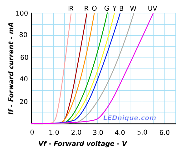
FWIW, 3.3V isn't necessarily correct for a specific white LED, they vary.  Here's a typical curve for various color LED's, as the color changes, so does the operating voltage.  Note that at 3V, the "typical" white LED is operating at 20ma, which is the "typical" operating voltage.  Also note that by the time you get to 3.3V, the current is already at 30ma, 1.5 times the operating current.  This will greatly shorten the life of the LED.

This graph is why I operate LED's using constant current as that allows much finer control of intensity and avoids the touchy voltage setting.

Image result for white led voltage current curve

MichaelB posted:

@Engineer-Joejust so we're clear. This is how you wired the lighting in your Horizon passenger cars?

Untitled

Yes I know this is a crude drawing, this is just so I have a plan when I start the project of converting all 5 of my passenger cars to LEDs.

Wow. I had to read thru all those old posts to see what I ended up with. Yes, it looks like what you've drawn is correct. I have two rail cars and I added a poly fuse in between the trucks for possible derails. I also have a choke inline to protect the DCS signal.

 I also need to re-mention that the backs of the red LEDs need to be masked off so that light from inside the car doesn't make them look like they're lit.

Engineer-Joe posted:

I have two rail cars and I added a poly fuse in between the trucks for possible derails. I also have a choke inline to protect the DCS signal.

 I also need to re-mention that the backs of the red LEDs need to be masked off so that light from inside the car doesn't make them look like they're lit.

I will for sure add in a poly fuse for protection. Does your board have a choke in it already @gunrunnerjohn?

I will also cover the parts of the LED with thick black paint. The red light bleed always annoys me with the cars, when I have the marker lights on.

The height is reduced to 1/2" by simply folding the tab on the regulator module, I specifically use the LM317 with the thin tab to allow this "modification".  I usually just stick them to the ceiling of the cars with DS foam tape, there's normally plenty of clearance.  Here's a RailKing observation car that illustrates the positioning and the tab folded over the cap.  Also note the wiring for the discrete LED's, those shine through the side markers and the rear tail-light of the car.  Extra lighting secured using hot glue in this case.

Attachments

Images (1)
  • mceclip0

I was asking about the dimensions, because I am considering using the heat sink from the current board as a way to mount the regulator board to the frame. The heat sink is a perfect size for the board/ That way I will be able to take the shell off in the future and only have to disconnect one or two connectors to get it off.

But that could change if I find problems with my mounting idea.

Last edited by MichaelB

Add Reply

Post

OGR Publishing, Inc., 1310 Eastside Centre Ct, Ste 6, Mountain Home, AR 72653
800-980-OGRR (6477)
www.ogaugerr.com

×
×
×
×
Link copied to your clipboard.
×
×