Can someone tell me if insulated rail joiners are used in connecting any of the rail ends of Atlas switches when connecting Atlas O three rail switches into a layout? With Lionel switches, insulated rail joiners are used on the inside rails of each of the two tracks that diverge from the switch, that is an insulated pin is used on the inside rail of the main line where it intersects with the inside rail of the turn-out rail.
Replies sorted oldest to newest
Nope no insulators.needed because the switch doesn't have a non derailing feature like the Lionel switches
No. Atlas non-derailing is based on spring tension on the points as opposed to triggering a solenoid like Lionel turnouts. If you want to trigger the points, you can use the Atlas non-derail board and an insulated section of rail near the turnout as demonstrated in this video:
Thanks to the both of you who replied to my question about the Atlas switch rail insulator question I posted. I really appreciate it!
You can add electric non-derail using the 6924 relay board and the two small sections of track near the frog of the switch, if isolated.
Atlas electric non-derail, from the Atlas website.
Mike, Thanks for this valuable information.
Mike,
Another question then comes to mind after posting a thank you. If I install the board you suggest, must insulated joiners be added as with the Lionel switches?
Thanks again,
Marc
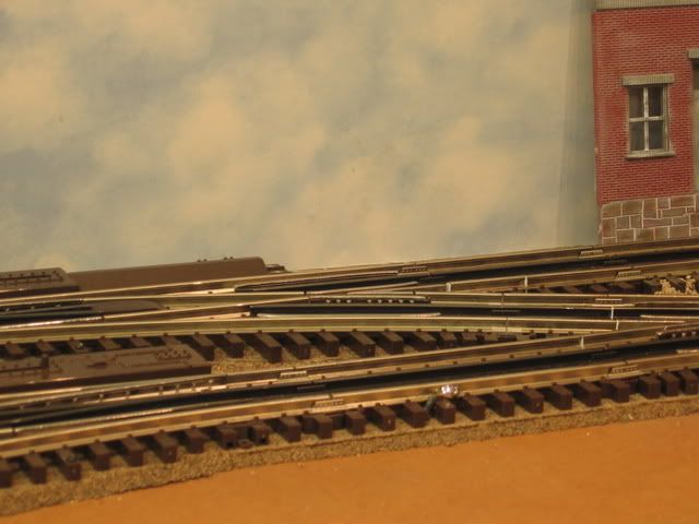
Yes, I did some extensive work on the insulated rail sections. Note the pieces of styrene strips as insulators. Atlas has insulated rail joiners (6093).
Also note the pieces of white styrene installed in this cross over isolating two different track circuits and providing the isolated rail sections for relay board input for non-derail.

Mike,
I see what you've done. If you don't mind, I'd appreciate your emailing me your phone number to my regular email address, in case I have any further questions. My email address is marcschuman@yahoo.com.
Thanks again for the lightening-fast responses!
Marc
Hi Again Mike,
I notice from the photos the green and red wires. These are track power, I assume. Is it necessary to power the switch with track power in addition to the power being supplied to the switch by the adjacent rails?
Marc
Hi Again Mike,
I notice from the photos the green and red wires. These are track power, I assume. Is it necessary to power the switch with track power in addition to the power being supplied to the switch by the adjacent rails?
The green and red wires are inputs to the 6924 relay board.
Note switch boards/switches #17 or #18. The top green and red wires (left on board) are isolated rail and, in my case, momentary input from an IC Controls ASC 3000, that will either trip the switch automatically, or with handheld Cab1/Command base control. Note the small grey twist connectors that combine the two inputs. The reference Atlas diagram also shows this dual input to the relay board.
Green Red upper right on the board is output to the switch. The board has a built in time out feature that inhibits switch motor burn out, a problem with these and other switches related to stuck push buttons.

Marc
Wow, Mike. You're a wiring guru, to say the least. I am operating MTH DCS command, using their accessory control modules for my switches. I'll have to study the Atlas wiring diagram carefully to understand how these #6924 boards would interface with my system.
Your information is very valuable, and I appreciate the photos.
Marc
The MTH AIU connections are shown on the first Atlas diagram I referenced. Those T's (Through) and O's (Out) get connected together. If you do a forum search/advanced search for 6924 or 6924 relay board(s) there are a couple of in depth discussion done the last few years. Best wishes with your project.
So that I understand correctly, you can put the isolated rail leg of the switch, the switch push button, and the lead from the SC-2 all to the same port on the screw of J1 and all three will throw the switch, and keep your switch motor from burning out from holding the button too long?
Hello Sinclair,
Since I've just started the first switch install on my layout, I am not completely sure I understand what you've written me, particularly as this relates to the AU-1 MTH DCS controller box, which just has three terminal posts per switch. Perhaps you could send me a simple diagram or give further verbal clarification, if you don't mind?
Thanks,
Marc
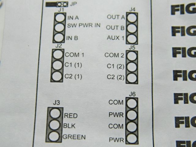
Note the small grey twist connectors in the picture. I uses 18 gauge solid thermostat wire to connect the switch and relay board. It was difficult to get (2) wires under the terminal on the 6924 relay board, so I combined the wires with a twist connector to one wire under the J1 (InA) terminal, green wires. The same is done with the wires to J1 (InB) terminal, red wires.

Typical non-derail wiring with an ASC 3000 from the Atlas website. Click to access wiring diagram. All the "T's", (Through input), are connected, and all the O's, (Out inputs), are connected.
Add wiring terminal detail 6924 relay board.
Hello Sinclair,
Since I've just started the first switch install on my layout, I am not completely sure I understand what you've written me, particularly as this relates to the AU-1 MTH DCS controller box, which just has three terminal posts per switch. Perhaps you could send me a simple diagram or give further verbal clarification, if you don't mind?
Thanks,
Marc
My question was directed at Mike (Thanks Mike, great to know.). And it looks like Mike just answered your question.
This is Marc again. I've looked at the Atlas wiring diagram referenced earlier by Mike CT. The Atlas diagram for the MTH DCS AIU shows the T and O inputs, which correspond to the 1 and 2 (straight and curved respectively) inputs on the MTH AIU. That leaves the "1N" input on the AIU without an indicated connection in this diagram. In the AIU manual, this input is called the "AC Ground" terminal. I tried connecting the center post of the Atlas switch to the AIU "AC" Ground Terminal and the outer Atlas switch wires to the T and O inputs on the AIU. After applying power to the track, and programming the DCS handheld to activate this switch nothing happens when the controls are activated for "straight" or "switched." I verified with a Lionel switch/turnout that the wiring and handheld programming are correct to operate the Lionel switch. Any ideas out there as to what I'm doing wrong?
Typical non-derail wiring with an MTH AIU
Mike,
Thanks so much for sending this link. If I choose NOT to use the non-derail circuit boards, which I am not finding locally, do you know how to wire the switches without the boards?
Thanks again,
Marc
Mike,
As you've figured out by now, I am most definitely NOT a wiring genius.
On the Atlas schematic you forwarded me, there's a common wire coming off the center post of the Atlas switch with a squigley ground symbol. Does this wire, go back to the common post on the transformer? I have an MTH Z4000 transformer with 14v DC posts. I am assuming I'd connect the common coming from the center post of the switch to the 14v transformer DC post. Is this a correct assumption?
Thanks,
Marc
Mike,
As you've figured out by now, I am most definitely NOT a wiring genius.
On the Atlas schematic you forwarded me, there's a common wire coming off the center post of the Atlas switch with a squigley ground symbol That would be the U terminal of the transformer you are using. . Does this wire, go back to the common post on the transformer? Yes. I have an MTH Z4000 transformer with 14v DC. Most likely this is AC but it should work for the Atlas switch motors. posts . I am assuming I'd connect the common coming from the center post of the switch Motor to the 14v transformer (Black) post. Is this a correct assumption? Yes. Take the red post wire to the pushbutton and then two wires from the push button to the Atlas switch motor. (Through and Out). These should be momentary inputs. Push and release the button. Extended power to the Atlas switch motors will burn them.
Test: With the Black terminal wire attached to the center post of the switch motor, take a wire from the Red terminal, of the 14 volt transformer, and touch it to the left terminal of the switch motor .(REMOVE IMMEDIATELY AFTER TOUCHING IT TO THE TERMINAL). The switch motor should have move. Try the same thing with the right terminal of the switch motor. It should move the other direction. If you have determined the switch motor will function. Now install the push button switch as the attached diagrams that came with the switch assembly indicate. (KEEP IN MIND THAT IF YOU APPLY PERMANENT, ON ALL THE TIME, POWER TO THE SWITCH MOTOR, THERE IS A GOOD CHANCE YOU WILL BURN IT).
It's unfortunate that the diagrams we are using involve the relay board/ non-derail function. There are significant differences in the wiring with out the relay board. Use the wiring diagram that came with the Atlas switch and associated push button that came with it.
Best wishes with your project.
![]() Mike CT
Mike CT![]()
Thanks,
Marc
Mike,
I again appreciate your suggestions. I tested the switch, and it works fine. I attach a primitive wiring diagram showing what I think is a partial solution to my wiring, but I am not sure it will work.
I presently have a three-wire run to each of my existing Lionel switches on the lower level of my layout. There are twenty of these, and they all work perfectly.
I roughed in eleven more three-wire runs to my upper layout level where I wish to use the prototypical Atlas switches, many of them wye's, not realizing that Atlas switch motors are not track-powered.
A fourth new wire is shown on the wiring diagram that would be run for one leg of the switch motor power, since an Atlas Motor is not track powered, unlike Lionel.
I believe the AIU relay either actuates SW1 or SW2, which controls the switch frog position.
Does the circuit I've drawn look correct to you?
I'd appreciate your thoughts and any suggested modifications.
Thanks again,
Marc
Attachments

Wow Again, Mike. Thanks for this suggestion. I'll try it and let you know!
Marc
Mike. You're a genius! It worked perfectly the first time I tried it this way.
Thank you very much for your wisdom, sir!
Marc Schuman
marcschuman@yahoo.com
Have a great day. ![]()
![]() Mike CT
Mike CT ![]()
Now I will have a great day!


