
The most basic two questions -


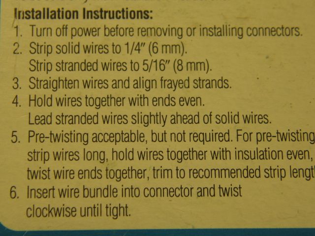
  1. Looking to connect the wiring from lights and other layout accessories to the buss wires I plan to run under the layout. What methods are most preferred?  I wired my rails for DCS via star pattern and every power drop runs back to the terminal block, so I never had to consider a good way to connect wires under the table to a buss. And the two books I have on wiring don't specifically discuss best methods.  Presumably, soldering is best, or those little suitcases.  But I can't solder upside down.
  2. Can buss wires be like a point to point?  Meaning, they start at the power source and terminate at the farthest accessory?  Or do they need to form a loop that starts and then ends at the power source? 

thanks!


Original Post

Replies sorted oldest to newest

GRJ - thanks for the reply.  Curious, how would you solder upside down under the benchwork?   Maybe the buss remains unattached on the terminus side to allow it to hang down for soldering? 

Also, I was thinking of the suitcases, but my buss is going to be either 10awg (because I have about 100' and want to use it somewhere!) or 14-16 AWG. In terms of accessories, wire can be anywhere from 18awg to 30awg. Not sure if suitcases accommodate that kind of variance in wires?

Thanks.

Peter

Upside down at least half way right side up.

 Layout wiring done on a ladder.

 Count all those black tape marks, each is a soldered connection.  Why would you risk hot solder under a layout???  There is more than enough types of mechanical connections that would do well if you wish to wire under a layout. Those who would question mechanical connection need to learn how to install them properly. Safety meeting of the day.  IMO. Michael C. Thompson.


Instruction listed on the box.  Ideal connectors.

 Those who would have problems twisting mechanical connectors there is a power tool adaptor that was available from Buchanon, now Ideal.

Last edited by Mike CT
Originally Posted by jmiller320:

       
I used this type of connector.  I used #14 wire with no issues.  Connect your power wire to one and connect your power drops to all but one of the remaining holes.  Use the last hole to extend your bus.  Available at Home Depot and other big box stores.


FYI - I'm standing in the electrical isle in HD - this type of connector only accommodates 12-20 AWG wire. Can't use for any accessory (which is many) that comes with 22-30awg.
Last edited by PJB
The other thing that occurred to me is that any sort of connector, like a winged wire connector, wouldn't, as far as I can tell, allow BUS (one continuous wire with other wires connecting to it) wiring. Wouldn't you need to cut the bus at every comnection point in order for it to go into the winged connector?  So I'd have really have three wires at every connection point - the accessory wire and then the bus "in" and the bus "out" that runs to the next connection point. No?

As Mike CT stated above, there's always wire nuts. Then there is the Wago connectors, they look really nice, but I have never really looked into them, neat idea though. And then there are terminal strips. I like the Euro style, they are inexpensive and you don't need crimp connects. Then the ones you have already mentioned, soldering and the suitcase connectors.

Originally Posted by PJB:
The other thing that occurred to me is that any sort of connector, like a winged wire connector, wouldn't, as far as I can tell, allow BUS (one continuous wire with other wires connecting to it) wiring. Wouldn't you need to cut the bus at every comnection point in order for it to go into the winged connector?  So I'd have really have three wires at every connection point - the accessory wire and then the bus "in" and the bus "out" that runs to the next connection point. No?

Yes, but nothing wrong with that, that's how your home is wired, and most all other buildings as well. They've been doing it for a long time, probably have all the bugs worked out. You just have to read the wire nut instructions and make sure you use the correct wire nut. Also easy to break apart for trouble shooting later on, should you have any problems.


Originally Posted by PJB:
Originally Posted by jmiller320:

       
I used this type of connector.  I used #14 wire with no issues.  Connect your power wire to one and connect your power drops to all but one of the remaining holes.  Use the last hole to extend your bus.  Available at Home Depot and other big box stores.


FYI - I'm standing in the electrical isle in HD - this type of connector only accommodates 12-20 AWG wire. Can't use for any accessory (which is many) that comes with 22-30awg.

Probably the smallest twist connector is Ideal (71B) Wire connector. Min (2 #22) to Max 2 #16. Small Gray wire nut.   Smaller wires, I suggest hand twist long, double the twist over and twist again.

These Ideal wire nuts (71B) are used connecting 22 ga wire to the small leads off a DZ 1000 switch machine.

 Complete detail on the 71B connector from the Ideal website.

IDEAL Wire-Nut® Wire Connectors

Model 300 Volt Maximum 600 Volt Maximum

71B®

Strip solid wires ¼”;

Strip stranded wires 5/16”

1 #14

1 #14 w/1 #20 or #22

1 to 2 #16

1 #16 w/1 #18

1 #16 w/1 to 2 #20

1 #16 w/1 to 3 #22

1 #16 w/1 #20 w/1 #18 or #20

1 #18 str.

1 #18 w/1 to 3 #20

1 #18 w/1 to 4 #22

1 to 2 #18 w/1 #20 w/1 #22

2 to 3 #18

2 #18 w/1 #20

2 #18 w/1 to 2 #22

1 #20 w/1 to 4 #22

2 to 4 #20

2 #20 w/1 to 3 #22

3 #20 w/1 to 2 #22

4 #20 w/1 #22

2 #22 str.

3 to 4 #22

5 #22 sol

Ideal 71B spec sheet.

Last edited by Mike CT
Originally Posted by rtr12:

Here's one more I have not yet looked into, but looked like a very nice device. I meant to order some to try out, but haven't done it yet. Forgot all about them until reading your post earlier. Posi-Tap


The link to them was posted in this thread, a similar discussion: https://ogrforum.com/t...r-track-tunout-power

Wow, that looks like a winner!  Seems it can accommodate and AWG wire drop and like a suitcase, allows it to connect to a bus, and easily disassembled if need be. 


Still in research mode, but looking like if these posi-taps turn out to be too good to be true, I will test try a few options.  Thinking I can wrap the accessory wires around the bus and then using liquid tape. Or the wing things. Or maybe suitcases that allow that level of variance is terminating wire versus through wire ...


Thanks  again everyone.  

If you go with Scotchlok for track power, you might also consider 567.  I think I'm going with those but I haven't tried them yet.  One side is 10-12 AWG and the other side is 14-18.  As I have the wire for a 12 gauge bus and 18 gauge taps I thought this might work best.


I'll have to think about those Posi-lock connectors now. May try both.

Originally Posted by Mike CT:
Originally Posted by PJB:
Originally Posted by jmiller320:

       
I used this type of connector.  I used #14 wire with no issues.  Connect your power wire to one and connect your power drops to all but one of the remaining holes.  Use the last hole to extend your bus.  Available at Home Depot and other big box stores.


FYI - I'm standing in the electrical isle in HD - this type of connector only accommodates 12-20 AWG wire. Can't use for any accessory (which is many) that comes with 22-30awg.

Probably the smallest twist connector is Ideal (71B) Wire connector. Min (2 #22) to Max 2 #16. Small Gray wire nut.   Smaller wires, I suggest hand twist long, double the twist over and twist again.

These Ideal wire nuts (71B) are used connecting 22 ga wire to the small leads off a DZ 1000 switch machine.


MikeCT - re-read the responses to my query - thanks again, this is really helpful.

Last edited by PJB

I looked at the posi-tap connectors and they are really nice.  Pricey, but nice.  The one issue, and it's the same issue as with the ScotchLok suitcases, is that I couldn't find one that allows a through wire of say 14 awg and the splice wire to be say even 26 (forget about if you need one for 28 or 30 awg).  


My bus will be 14 awg or maybe 16 awg and accessories can vary from 18 to 30 awg.  Curious if it would be ok to simply solder to the end of each accessory wire a short length of say 18- 22 awg?  If so, this would allow me to use either the posi-tap or suitcases.  Or is this an electrical no-no??


Peter 

Last edited by PJB

Another point that was not detailed in this tread.  With some planning you can make most connections (Soldered above the layout)  Pull the feed wire through a hole near the accessory make the connection, and push the wires back through the hole. Scenery should cover the hole.  Use a little more wire to a common terminal point and make buss connection in a convenient location. 


Those familiar with the Mercer Junction Train shop, I spent a couple of days wiring the switches/turnouts. One day above the layout doing soldered, non-derail drops, and isolation rail sections.  A second day connecting DZ1000s switch motors, and the push buttons.  I used a lot of the 71B connectors mentioned above, no soldering under the layout.  You still have to deal with sitting under the layout, working with your hands over your head, or at the least, eye level.  Makes for a long day.  IMO 

A few pictures of the Mercer Junction layout


Another helpful tip, (maybe?), for those working with bifocals, attempting to look up at those wires above your head.  Put the glasses on upside down, bifocal section to the top.  I had an optometrist tell me he has done glasses with an additional bifocal part to the top of the glasses for those working over there head a lot, common in my profession. 


At the very least, any eye glasses afford some degree of eye protection. Safety meeting of the day.  

Last edited by Mike CT

I used the Euro style terminal strips for most of my connections. Cut off the number you need for your connection. I used the smaller ones to extend FT  switch controller wires and larger for feeders. Wire size is very flexible and jumpers work for multiple taps. It is not very easy to strip bus wires in the middle without nicking the wire or taking off more than you need while always working over your head. The strips are also easy to disconnect for trouble shooting or removing accessories to work on them.

As you can see, there are many ways of wiring that accomplishes the same objective- and perhaps there is no perfect solution.


What has worked best for me is to use inexpensive bus bars who sole purpose is to connect a lot of wires together. I get them at home depot. I placed 4 pairs of them around the underside of my layout to keep wiring from lights short and convenient. Pairs are needed because you need one for + voltage, and 1 for - voltage. I happen to use 12 VDC for all my lights because 12V power supplies are easy to find, the bulbs last a long time on 12V, and I can interchange LED or Incandescent without rectification.


These bus bar are inexpensive and quick to connect to which minimizes my time under the layout. Not so easy to crawl around and see close up anymore. Also easy to change later if accessory placement changes.


Bob

A quick question to Allentown Bob:  can you tell me the mfg and part number for the Home Depot bus bar that you mentioned in your post?  I am beginning to wire my 16x20' layout and haven't been able to find one that would work.  


For those that use "suit case" connectors: I found a NAPA connector, part #725208, that handles 10-12g with a t-tap female connector built in that will accept a blue male connector (16g wire).  My bus wire is 12 g and both my power and neutral drops are 16 gauge.  Having said that, I still want to use a bus bar to help split the runs up in trouble-shooting, should that (likely) become necessary.


------------------------------------------------------

"Model Trains, where men become boys again"


A quick question.  Back in the 70's the electrician's at the plant I worked at use a connector similar to the Ideal wire nut.  It was simple and worked well.  There was a outside threaded brass core with a locking screw inside large enough that you could use 3 or 4 different wire gauges. Place the stripped wires into the locking nut, tighten and then screw on the inside threaded insulated cap. Don't remember the brand, could have been Ideal. Has anyone seen these around lately?

Thanks

Tommy     

Add Reply

Post

OGR Publishing, Inc., 1310 Eastside Centre Ct, Ste 6, Mountain Home, AR 72653
800-980-OGRR (6477)
www.ogaugerr.com

×
×
×
×
Link copied to your clipboard.
×
×