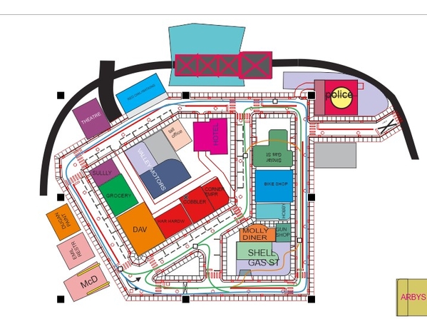
My upper level city design is progressing. Now I know why I am not a city planner.

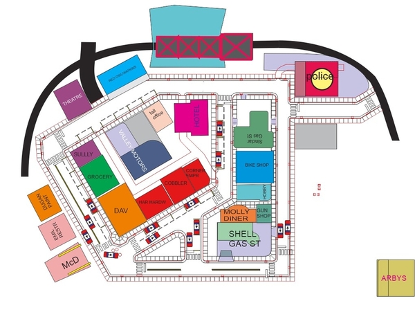
CITY OVERALL 2

CITY CLOSE

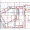
The City Model is in CorelDraw. The drawing is done in actual size of the 1/4 scale city. Once compete I will use it to make Laser Cuts of the streets and sidewalks then reassemble in to the whole city.

The Woodland and Menards buildings, cars and sewer grates provide guides and orientation  to making and cutting the streets and sidewalks.

Attachments

Images (2)
  • CITY CLOSE
  • CITY OVERALL 2
Original Post

Replies sorted oldest to newest

CITY CHOPPED

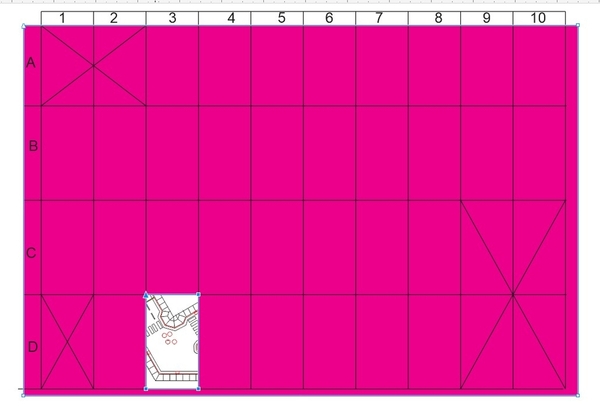
My upper level city roadways and sidewalks looks like this in laser cut grid. What is shown above is the laser cut squares. Each square will be laser cut and fits together like a puzzle on the supporting surface. I did modify the building locations from what is shown on the earlier thread above.

So the way this is done on CorelDraw (or any other graphics program) is to create a movable window the size that the laser cutter can cut. Then remove all details outside the window, leaving the parts within the window to send to the laser cutter.

CITY CHOPPED D3

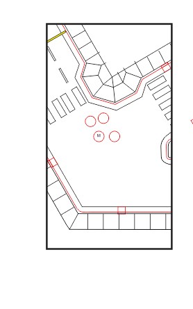
The above is grid square D3


D3

The above square D3  is converted to a .svg file that my GlowForge laser cutter will cut.

the black lines shown are scored for sidewalk joints and the red lines are the curb cuts and storm sewer grates openings.

This looks more complicated than it really is. The process is fairly straight forward.

Attachments

Images (3)
  • CITY CHOPPED
  • CITY CHOPPED  D3
  • D3

Also I have the AUTOMOTIONFX paths for my Automotionfx cars designed.

I will laser-ENGRAVE these paths on the reverse side of the roadways to fit the magnetic/iron rods that will be placed into the engraved paths underneath. So to do this I will take my laser square designs and MIRROR them to detail the underside engravings.


I believe that AutomotionFX uses a GlowForge to create their roadways, since their roadways are made from GF 1/8" draft board.

This Grid-Window Method can be used to laser cut much larger objects than the laser cutter bed size supports.

Super streets is limited to the street track pieces. AutomotiveFX  unlike the HO version of it used in Europe is also limited to their track pieces.

However, when I laser cut and engrave my own track pieces there is no limitation, except as to the turning radius and size dimensions of the specific AutomotiveFX car or bus or truck so equipped.

I purchased several switch-tracks from AutomotiveFX to incorporate into the paths; like going into and out-of the gas stations.

city all layer

All layers on this view; the image is separated into several layers to facilitate cutting; a street layer and a curb and sidewalk layer.

The street will be laser cut from 1/8" draft board like MDF, the curbs and sidewalks from 1/4" draft board; the curbs will be then routed for a curved edge to the street.

The street and curbs will have cut-outs to fit the 3D printed sewer grates and sewer covers. The street markings and walkway marks will be cut out and replaced with colored acrylic shapes in white and yellow.

Attachments

Images (1)
  • city all layer

city all layers w FX

City all layers shown. To laser cut I separated the elements into layers. the streets layer is 1/8" thick draft board shown below.

as stated above the layers are separated into rectangular Panels to be laser cut. The black lines shown below are scored the red lines are cuts.

All of the street markings are cut. these cuts are filled with yellow and white acrylic to represent the street marking colors. Sizes of markings are scaled per New York Highway Department Street mark standards.

the other sewers and street manholes are filled with 3D laser printed sewer covers and storm grates shown in other threads.

sewer cover

grate in place

the exact size of the cuts comes from a .DXF image of the top view of the 3D model in Rhino 7 superimposed into as a 2D image into Corel Draw.

the streets and sidewalks painted concrete gray.


city streets only

Sidewalk layer is cut from 1/4" thick draft board

city sildwalks only

Automotion FX paths, these paths are for the magnetic wires. the paths are laser engravings engraved in the UNDERSIDE of each panel.

to engrave, the image below is mirrored, and the reverse side of the panel is engraved with the wiring engrave path. Each panel will have its associated wire(s) installed so that when all the street panels are all in place the Automotion FX wire paths will connect.

I have several Automotion FX switches that will be used to re-direct the cars in different paths as well as into (and out of) each gas station shown below.

city automotive FX paths

Attachments

Images (6)
  • city all layers w FX
  • city streets only
  • city sildwalks only
  • city automotive FX paths
  • sewer cover
  • grate in place

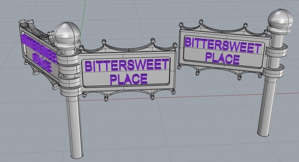
3D printed Street sign designs


street signs

These street signs will either be on or connect to hollow brass tubes or attached around traffic signals.

The top and bottom designs shown hide tiny LEDs that will shine down and up onto the letters.

The letters shown are 3D printed with the sign frame, however they may be CLEAR acrylic engraved to better reflect the LEDs.

the next step is to layout sidewalk streetlights, traffic signals, tree grates hydrants,  street name signs (above) etc for the insertion holes to be laser cut.

Attachments

Images (1)
  • street signs
@AlanRail posted:

3D printed Street sign designs

These street signs will either be on or connect to hollow brass tubes or attached around traffic signals.

The top and bottom designs shown hide tiny LEDs that will shine down and up onto the letters.

The letters shown are 3D printed with the sign frame, however they may be CLEAR acrylic engraved to better reflect the LEDs.

the next step is to layout sidewalk streetlights, traffic signals, tree grates hydrants,  street name signs (above) etc for the insertion holes to be laser cut.

Alan, Those are great looking. Your continued innovation is really impressive.

Last edited by Dave Ripp.
@AlanRail posted:

Hydrants with chains printed as a group.

I use the supports to hold the hydrants in place for painting.

there is a stem below to insert into sidewalks.


Close up. Actual height is 0.73" or 32" (1/48) scale.

chains attached to the three covers are discernable as links; note bolting.


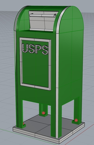
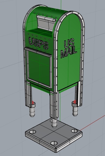
Alan, Your hydrants and postal boxes look better than any I've seen printed.

talk about time!  My last post on my upper city was in December. So I have progressed!

I chopped up the city into rectangular pieces to laser cut on my Glowforge. It looked like this.cut up
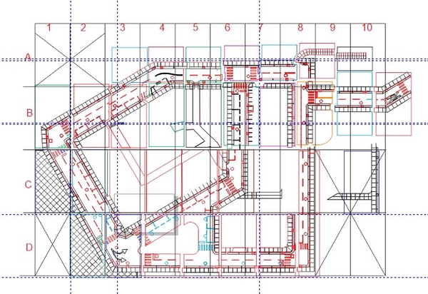
Each rectangular square is about 11"x18" the max cutting size of the Glowforge.

My first thought was to cut the sidewalk and curbing in 1/4" draft board (MDF like) and then recut the streets in 1/8" draft board, using a table router to make the rounded part of the curbs.

Instead, I cut all of it using 1/4"; and then  will raise up the sidewalk and curbs about a 1/8" to match the top of the 1/4" streets. This allows me to run wiring under the raised part for the streetlights and traffic signals without further grooving.

The upper city assembly is like a complex large puzzle.

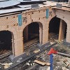
The upper city is sitting on Masonite that is attached to a framework of 1x3s, To hide the exterior 1/3s, I created, and laser cut a series of stone arch ways and several large bridges.
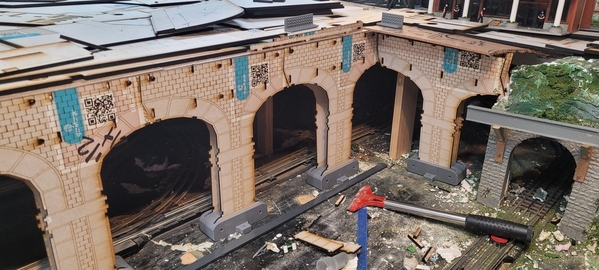
upper city arch 1upper city arch 2upper city arch 3

The 1x3s are hidden with  a combination of brickwork on the arches, The arch bases are 3d printed.

The arches will appear solid after the end pieces are attached.

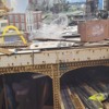
Below are the large bridges that span the inner river harbor (not shown) and track. These bridges are doubled outward to create thicker bridge effect (not shown). As shown, the arch brick work continues around to the bridges.

In this photo you can see the unassembled sidewalk, curb and street pieces waiting for assembly.

upper city bridge

Attachments

Images (5)
  • cut up
  • upper city arch 1
  • upper city arch 2
  • upper city arch 3
  • upper city bridge
@coach joe posted:

If I remember correctly the green mailboxes contained mail being delivered by the letter carrier, no slot just a locked door on on side, and the boxes for depositing mail were blue.

I have been a Postal worker for almost 30 years. Coach Joe is correct here with the exception that the locked door on the green box was on the front not on the side. Sometimes the green boxes were right next to a blue box and sometimes they were placed by themselves. A truck driver or a different Letter Carrier will fill up the green box in the morning with mail that is in walk sequence and then later on another Letter Carrier would work out of the green box by delivering the mail that was in the green box. This usually took 3 or 4 several loops where at the end of each loop the carrier was back at the green box. This has been my experience in NJ. Sorry I just saw prrhorseshecurve's response. He is correct they were called relay boxes.

Last edited by Hudson J1e
@AlanRail posted:

talk about time!  My last post on my upper city was in December. So I have progressed!

I chopped up the city into rectangular pieces to laser cut on my Glowforge. It looked like this.cut up

Each rectangular square is about 11"x18" the max cutting size of the Glowforge.

My first thought was to cut the sidewalk and curbing in 1/4" draft board (MDF like) and then recut the streets in 1/8" draft board, using a table router to make the rounded part of the curbs.

Instead, I cut all of it using 1/4"; and then  will raise up the sidewalk and curbs about a 1/8" to match the top of the 1/4" streets. This allows me to run wiring under the raised part for the streetlights and traffic signals without further grooving.

The upper city assembly is like a complex large puzzle.

The upper city is sitting on Masonite that is attached to a framework of 1x3s, To hide the exterior 1/3s, I created, and laser cut a series of stone arch ways and several large bridges.
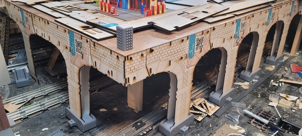
upper city arch 1upper city arch 2upper city arch 3

The 1x3s are hidden with  a combination of brickwork on the arches, The arch bases are 3d printed.

The arches will appear solid after the end pieces are attached.

Below are the large bridges that span the inner river harbor (not shown) and track. These bridges are doubled outward to create thicker bridge effect (not shown). As shown, the arch brick work continues around to the bridges.

In this photo you can see the unassembled sidewalk, curb and street pieces waiting for assembly.

upper city bridge

Magnificent!

Peter

Add Reply

Post
×
×
×
×
Link copied to your clipboard.
×
×