Replies sorted oldest to newest
Forum member Mike CT (might be MikeCT) has posted on the Atlas stuff several times. He is pretty knowledgeable in this area. If you search some of his posts you might find something? If not maybe he will be along shortly to post here. I am thinking of doing the same thing, will be watching this also. I don't have any of the parts or switches yet, so it will be a while for me.
PJB,
I'm not sure if I fully understand your question, but I think you are pondering how a switch enters into Barry's rules for star wiring, etc. As far as star wiring is concerned, just consider a switch as a piece of track, even though it has 3 connection points. Barry's rules of 5 connectors or 5 feet of track either side of a star feed doesn't really care if there is a switch in there, 6924 controlled or not. I use a lot of #5's and O54/O72 switches with 6924's used to power the closure rails to prevent loco stalling.
Atlas switches do have poor wiring connections, and I always go over mine before I install them and beef up the internal switch wiring as needed. The switch internal wiring issue is not that much of a problem when you wire to DCS rules - there is almost always power getting to the switch from other feeds.
Rather than babbling on, here's a sample of how I have wired my layout for DCS.
In this section of layout, the orange circles represent star feeds from an MTH distribution block (the rectangular orange object in the middle), which in turn is fed by one TIU output. (The black circles around some of them means that those feeds are fed through a relay contact so I can shut down sidings). Insulators are represented by blue dots. You can see that switches are just another piece of track as far as DCS is concerned.
Hope I didn't misinterpret your question and confuse things further!
Regards,
Gary F.
Attachments
I'm very late to the table with DCS on my layout. I did recently add DCS and it seems to operated with no issues. It is added in passive mode, supplying signal only to the system via the Fixed Out #1 terminals.
There are (21) 6924 relay boards operating (25) switches. There are also two IC Controls BPC's (Block Power Controllers) that the DCS operates through.
Along with the auto non-derail feature each Atlas switch is controlled via a Cab 1 remote and early IC controls ASC's (Accessory Switch Controllers)
DCS recently added.
I did nothing special related to the 6924 relay board installations to accommodate DCS. All Atlas switches are wired for auto non-derail feature and all have power routing added. There are (4) cross over switch combinations that are operated by one 6924 relay board for two switches. (21) relay boards (25) switches. I also added track power fusing at each relay board (3 amps), even with the boards rated at (8) amps I had issue with 6924 relay board trace burn out on dead short derails.
Relay board installation.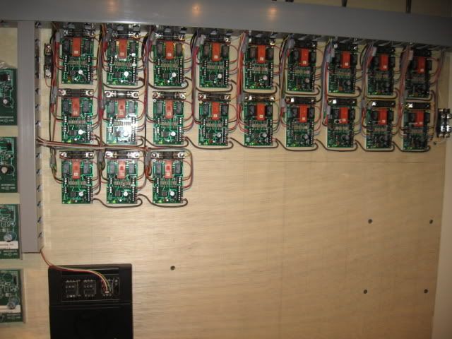
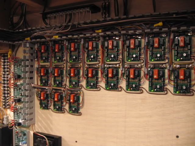
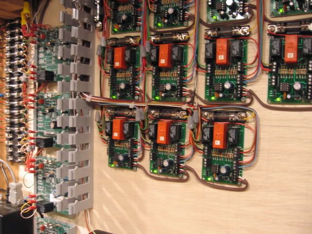
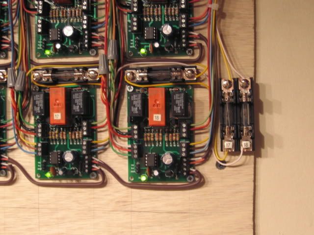
Switch wiring. Non-derail input.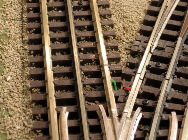
Power routing out.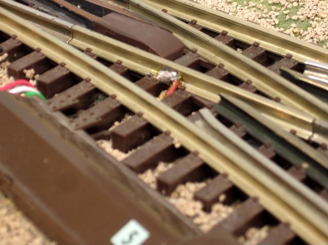
Grandson Micah's MTH Proto2 GP20
Peter,
The 6924 is a switch controller. It has nothing to do with DCS or DCS star wiring. Think of the 6924 as totally independent of DCS.
Here's a little more detail on the wiring example I gave: This shows one of the TIU outputs connected to an MTH terminal strip (50-1014). The terminal strip, in turn, feeds each of the DCS blocks at the point shown by the orange circle. Each DCS Block is defined by the blue dots representing center rail insulators. Note that each orange feed is more or less central to a group of track sections isolated by the blue insulators. i.e., by Barry's Rules there should be about 5 sections of track (or about 5 feet) from the central orange feed to each of the blue insulators. Note that the MTH terminal strip is also the ideal place to put the DCS "magic lamp".
Please don't consider this diagram as the only way to wire DCS, it's just an example that shows the basic concept of star wiring.
Here is a link to a schematic of how I wire the 6924 for closure rails with anti-derail.
https://ogrforum.com/t...37#16494189560377437
Attachments
You might try this drawing from Atlas website?
http://www.atlaso.com/pdfs/POW...ING%20USC%20copy.pdf
To try and clarify, make your block with your switch in it, feed that block with 1 power drop from your dcs terminal strip as per Barry's book. Then all the wiring within that 1 block is 1 drop. If you feed the circuit for the closure rails using track power within that block you are still following the dcs guidelines. Think of the power to the closure rails as rail joiners, track connnectors, etc. just joining the tracks together, not as a separate drop.
If you ran another drop from your terminal strip for this, that would be 2 power drops and would not be following the guidelines. Operation of the switch motor itself would be separate power and a separate circuit, having nothing to do with track power. This is the way I see it, and may possibly help you with your understanding?
If there is an error in my logic here, someone please correct me as I don't want to lead anyone astray, just trying to help clarify a bit. I am still learning as well, and not real good putting at my thoughts into written words.
For the switch legs, just jumper them to the adjacent powered section and not to the power feed directly. It'll be like a track connection.
You're welcome. I would definitely go with Barry's direction rather than mine, as he "wrote the book". I'm planning on using Atlas switches and will also be using the 6924's. Others have advised replacement of the under switch wires. Guess I need to break down and get a switch or two so I can see them first hand. Don't have any yet, spent all my train funds on engines & car sets from the most recent MTH catalog. Please let us know how it all works out for you.


