Hello Im new to the forum new to O gauge. My father was into O gauge and recently passed away so I inherited his layout. I have everything hooked up and am working out the bugs out. His whole layout was MTH running the DCS system. The track is Atlas with Atlas switches. Have been checking all the track voltage and continuity through out the layout. I noticed that at the Atlas switches I was loosing continuity so I soldered jumpers where I thought they needed to go and it has helped with the dead areas except for one switch. If I run the MTH diesel that he had it gets through that area with no problem and at a low voltage of about 7-8 volts. If I run his MTH Steam Engine through that section at around 8-9 volts the engine completely stops in that section. If I run it at 11-12 volts it goes through that section with a slight pause. Ive cleaned the engine pickups and lubed them. I also have cleaned the track. These switches are probably at least 10 years old.
Replies sorted oldest to newest
What is the size of the switch? 042, 054, 072 or something else. Is this the only switch of that degree that it stops on. In other words if this is a 054 switch does it pass through other 054 switches. If this is the case then the switch is the problem. Early on in the production of their switches Atlas had a problem with the wire jumpers under the switch that fed the center rail. One problem was the jumper wires were too light and would burn up. The other was the jumper connections themselves were poorly connected. Looking at the switch from the facing point end there is a short center rail then after that there is the section that is v shaped on the center rail. The jumper between those 2 sections was one trouble spot. From that point there should be a jumper to the 2 trailing point center rails. This is another trouble spot. I drilled a small hole into the bottom of the center rail were the jumpers are and soldered heavier wires between these points. The hole gave a better surface for the solder to adhere. One end of the existing jumper looks to be tack welded on. This was usually the point of the trouble. Try to use at least 16 gauge wire if you need to make this repair.
Then again if this is the only switch of this size that causes the problem check the position of the pick up rollers of the engine to the location of the gap on the center rail of the switch. Also use an ohm meter and check that there is continuity between the pickup rollers of the engine. If that is the problem I would think it would stall on any switch though. It was my understanding that center rail gap problem was mostly on the large #5 and # 7.5 switches and the ones that had both tracks curved like the 072/054 switch.
Forest.
Actually I'm having problems with the majority of the switches. this i the only one that is still giving me trouble on the lower section. As I try to get to the next level there are dead spots in two other switches. I can supply pictures. Thank you so much for your help. This has been a great learning experience. How do I tell the size of the switch?
Without being there in person to inspect the turnout, my best guess is that the wiring that connects the center rail to the diverging center rails is bad. If you examine the turnout more closely (in the red circle), you will see where the diverging center rail casting is separated from the center rail leading into the turnout. Run a continuity check placing the probes as indicated by the yellow dots. If there is no continuity, turn the turnout over and check the wire for continuity. If you still cannot get a reading, I would replace the wire.
When I replace the damaged wire on another turnout, I soldered the replacement directly to the rail. Soldering to the side of Atlas black rail is not too difficult. First, you need to prep the rail by sanding away the black coating until you see shiny rail. The next step is to tin both the rail and wire you are using. Coat the rail with flux to help the solder flow. Remember, the ties are plastic, so me mindful of how long the soldering iron is in contact with the rail.
Hope this helps!
Attachments
keith scoskie 122018 posted:How do I tell the size of the switch?
Hold the turnout upside down under a good light source.
Attachments
I have a few atlas switchs and have run into that problem.You see I had a mix of atlas and gargreaves track.After a while of having my trains just stop in many places along my layout.I went back to all gargreaves.I do not have dead spots any more.So If I where you I would go with gargreaves all the way.
You can fix the Atlas switches as detailed above, that's probably the path of least resistance.
If you don't want to fool with the switch, you could also have an extra pickup roller added to the tender by an experienced MTH service technician. IMO, it should have had at least 3 rollers in the first place! Then, if any other switches develop a problem, or you bring the loco to another layout, it will perform reliably under all conditions.
I had the same problem Chessiefan72 identified some years ago on a couple of O72 turnouts. Initially I folded a short and narrow piece of soldering strip to jam in between the short rail and the longer rail for a quick fix. Later I added a wire to bridge the bad connection. If soldering is a problem, I recall an old post that described drilling a very small hole in the flange of the center rail inserting the end of the wire and then inserting a screw. Hope you get it fixed soon and back to running trains.
Wow guys that is great information. Thanks. I will work on it over the weekend and let you guys know how it goes!
well guys I checked the continuity to the track that had the dead spot and it checked out. I still made a jumper just in case and it did not do anything so i removed it. It seems like I am have most of the problems across the switches with the steam engines. The diesel engines move through it without any power interruption. I guess adding a pickup on the steam engines would be the way to go. Any other suggestions on how I can make the track run better and work with most of my engines? Ive cleaned it and have fixed most of the gaps that have developed on the layout. I have also checked the voltage with my meter and it seams very consistent.
Attachments
keith scoskie 122018 posted:well guys I checked the continuity to the track that had the dead spot and it checked out. I still made a jumper just in case and it did not do anything so i removed it. It seems like I am have most of the problems across the switches with the steam engines. The diesel engines move through it without any power interruption. I guess adding a pickup on the steam engines would be the way to go. Any other suggestions on how I can make the track run better and work with most of my engines?
The key is to measure the spacing between your model's pick-up rollers, and compare that dimension to the gap in the Atlas turnouts, i.e. the "dead spot" in the center rails where the frog is. If the length of the "dead spot" is longer than the distance between the pick-up rollers, the the model will stop on that turnout. I remember having to add an additional pick-up roller assembly on the tender of one or two of my MTH steam locomotives, in order to insure smooth operation over all my Atlas #5 1/2 turnouts.
Ive cleaned it and have fixed most of the gaps that have developed on the layout. I have also checked the voltage with my meter and it seams very consistent.
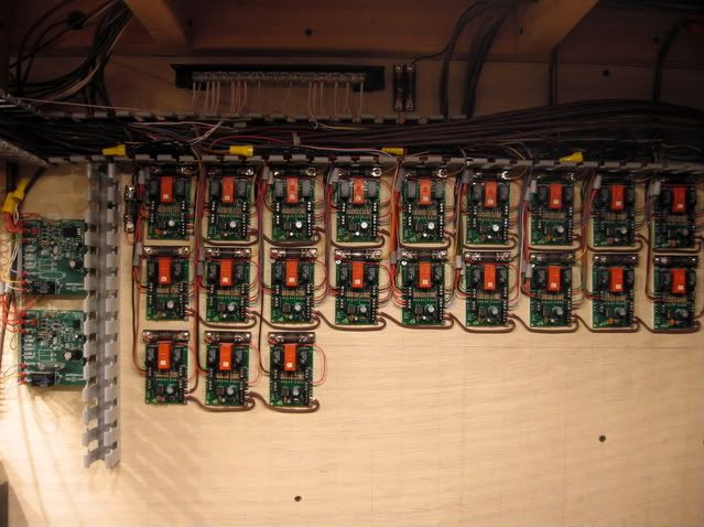
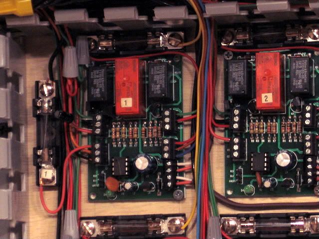
If you can find them, Atlas had done a relay board designed to power route through their switch, logically eliminate the dead spots. I had installed 23 of the 6924 boards. The board(s) also added other switching features, Non derail function, and signal indication to Atlas switch motors. A time out feature, built into the board, eliminated Atlas motor burn-out, an early problem with Atlas switches.


I've been reading about insulated frogs and the problems that they can cause. These are Atlas switches. Is there a manufacture that makes the insulated frogs without the dead spot problems that is compatible with Atlas track?


