This is a post about ways to control smoke units, electrocouplers, and other high current loads with a DCC decoder. No decoder that I'm aware of does those things 'out of the box', at least with the typical O-scale locos, so a little creativity is required. This will be based on what has worked well for me with the hardware I use. I'll cover the electrical hardware and configuration first, then discuss ways to configure an ESU Loksound decoder to achieve various results. I'll also provide a few examples showing different implementations with specific hardware. I'll probably end up doing this in a few sections, as time permits...
(Sneak preview though... One of the examples will show how to achieve fully functional smoke unit and electrocoupler control, with synchronized chuffing, speed sensitive diesel smoke, etc. using about $10 in commercially available parts.)
Hardware Overview
Most DCC decoders are not designed to drive high current loads other than the motors. 'High current' in this context simply means anything greater than the rated capability of the decoder's function outputs. For a lot of smaller decoders, this is around 100mA. For the Loksound decoders I use, they are rated as follows:
- Loksound V4 (HO): 250mA per output, 500mA total
- Loksound L: 500mA per output
- Loksound XL: 250mA per output
The typical loads in an O-scale locomotive are:
- Smoke fan motor: roughly 30mA continuous, a few tenths of an amp peak
- Smoke heater: 0.5A to 0.75A (around 2.5W to 3.5W output at 5V)
- Electrocouplers: 1 to 2 amps while actuating
So apart from the smoke fan motor, some additional hardware is required to allow a decoder to drive the usual O-scale doodads. This hardware needs to provide three main functions - getting DC power from the track DCC signal, efficiently converting that to a usable voltage (typically 5V) for the loads, and controlling it in some way from the low level outputs on the decoder.
The diagram below shows a general approach for making this happen. The items in orange - the rectifier, regulator, and power switches, will be discussed in detail below. The motor, speaker, and lighting control are all pretty standard, so I won't get into those items.
Decoder Function Outputs
DCC decoders for the most part use a 'low side switch' configuration for their function outputs, with the load connected to the supply voltage and the switch between it and ground. So when the function is 'on', the physical function output is grounded, or 'low'. When the function output is 'off', it is open, or floating. This has a couple of implications.
First, it influences the selection of the power switch. To keep things simple, it's useful if the logic of the power switch matches the logic of the decoder. That is, the power switch should be 'on' and providing power to the load when the function output is 'on'. There are a lot of devices that can be controlled by a microprocessor to switch larger loads, but many of them are configured such that they are 'off' when their control input goes low. However, it turns out that a p-channel MOSFET is well suited for this, as it is 'on' and conducting when it's input goes low. It's what I'll call 'logic compatible' with the decoder function outputs - 'on' at the decoder means 'on' at the power switch.
Another useful feature of the 'low side switch' configuration is that it is possible to combine multiple function outputs to control a single power switch. Because the function outputs simply provide a path to ground, they can effectively be superimposed to combine multiple effects. This allows for a lot of flexibility and some neat combinations of effects. I'll detail this approach in one of the examples.
DC Power
So, back to the diagram above, the first step is to get DC voltage from the track power. One of the really clever features of DCC is how easy it is to get DC output from it. A simple bridge rectifier gets you 95% of the way there. Ideally add a small cap (5uF to 10uF) and resistor and you have DC voltage more than smooth enough for model train purposes.
For a simple installation using cheap off the shelf parts, just about any bridge rectifier with a continuous current capacity over 1A will do the job. Wire the rectifier output to the regulator input and put a 10uF cap across it. The regulators below make it easy to do this. Then just wire the track input to the A/C inputs of the rectifier. The output voltage will be 1-2VDC below the DCC track voltage, depending on the rectifier.
For my installations, I designed a small PCB that I refer to as the power inlet board. It has a rectifier, cap and resistor circuit for providing DC output. It also has a TVS diode on it for a little extra protection for the decoder, as well as provisions for screw terminals in cases where they are handy for wiring up the track pickups. I can post details on this at some point, if anyone is interested.
Both of these approaches will feature in the examples.
Regulators
The rectified track voltage is going to be around 14-15VDC. In most cases, this will need to be reduced, typically to 5 or 6 volts. A linear regulator will generate a lot of heat with that kind of reduction, so I use a switching regulator. There are a ton of them available to choose from. Here are three that I've used.
- eboot MP1584 converter: This is my go-to in most cases. It's adjustable, with an input voltage of 4.5V to 28V and an output voltage of 0.8V to 20V, and rated for 3A output current. The adjustability makes these usable for just about any brand or era of smoke/coupler/whatever. Components are mounted only on one side, so it's easy to stick just about anywhere with some kapton and double sided tape. It's not the smallest of the ones I've used (22x17 mm), but it fits anywhere I've needed it so far. Available in packs of six for less than $10. This one will be used in various ways in all the examples.
- Murata 5V/1.5A converter: I used this one extensively in my arduino turnout project, and it's a good candidate for mobile installations as well. 5V and 1.5A output is more than adequate for most purposes. It is smaller than the eboot one, particularly if you remove the pin header. It has components on both sides of the board, however, so mounting it isn't quite as elegant.
- Pololu regulators: Pololu makes a bunch of regulators in various voltages and current capacities. In most cases 5V is what is needed, so something like this 5V/1A unit is a good choice. They are compact and have the components on one side, so they are easy to mount. They are a bit more expensive, however.
Power Switching
Now, to enable the decoder to actually control the load, a switch of some sort is needed. It needs a high output current capacity, and low control current demands. Ideally, it should also have a switching time fast enough for use with a PWM input, and should be compatible with inductive loads, although these features are not required in all cases. There are a lot of ways to do this.
- Mechanical relay: A mechanical relay could be used in the case where a simple on/off function is acceptable. I don't recommend this, however, as they are big, slow, and difficult to wire up nicely. There are many better options.
- Commercial MOSFET boards: Pololu makes a nice line of MOSFET power switches. Here is one that I've used. It's small and cheap, has a 3A current capacity, and is easy to wire up. It's a p-channel MOSFET, so it is 'logic compatible' with the decoder. It is not suitable for PWM use, as the on/off times are around 10-20ms. It does not have a freewheel diode for inductive loads, but it is easy to add one, as the board has two solder pads each for the output power and ground.
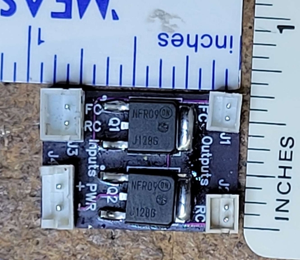
- Custom MOSFET board: Since I anticipated doing a lot of this in various decoder installations, I designed a simple 2-channel MOSFET power switch board. It has two independent control channels, so it can be used for heater/fan control for a smoke unit, or for powering a pair of front/rear electrocouplers. It uses a p-channel MOSFET, so it is naturally 'logic compatible' with decoder outputs. It is very fast, so it's PWM compatible, and incorporates freewheel diodes for use with inductive loads. I'll post some details on this in a separate topic.
- Regulator enable: Not strictly a switch, but there is an easy way to provide on/off functionality on the eboot regulator described above. The MP1584 chip has an enable pin. If it is left floating, the regulator output is enabled. This is the default configuration. But if it is grounded, the regulator output is disabled. To use the enable, I solder a small wire directly to the enable pin on the chip. The control logic will be reversed, unfortunately - the regulator will be on when the function output is 'off', and vice versa, but this can be accommodated to an extent with the Loksound configuration. This is a really cheap and easy way to provide a controllable, fixed-voltage output.
So that covers the general idea, as well as some specific hardware components, that can be used to drive larger O-scale loads. These can be configured in a lot of ways, of course, depending on the specific installation, so I'll go over a few examples in a later post.
Up next, decoder configuration...


