Replies sorted oldest to newest

Actually, it's less work with Fastrack, all you have to do is remove the cross links and you have insulated tracks.  With tubular track you either kludge some insulators under an outside rail or you buy insulated track sections.  You also have the purchase option with Fastrack.  I like the relay to have some bounce protection so you don't get a blinking light when you're entering or leaving the insulated track section.

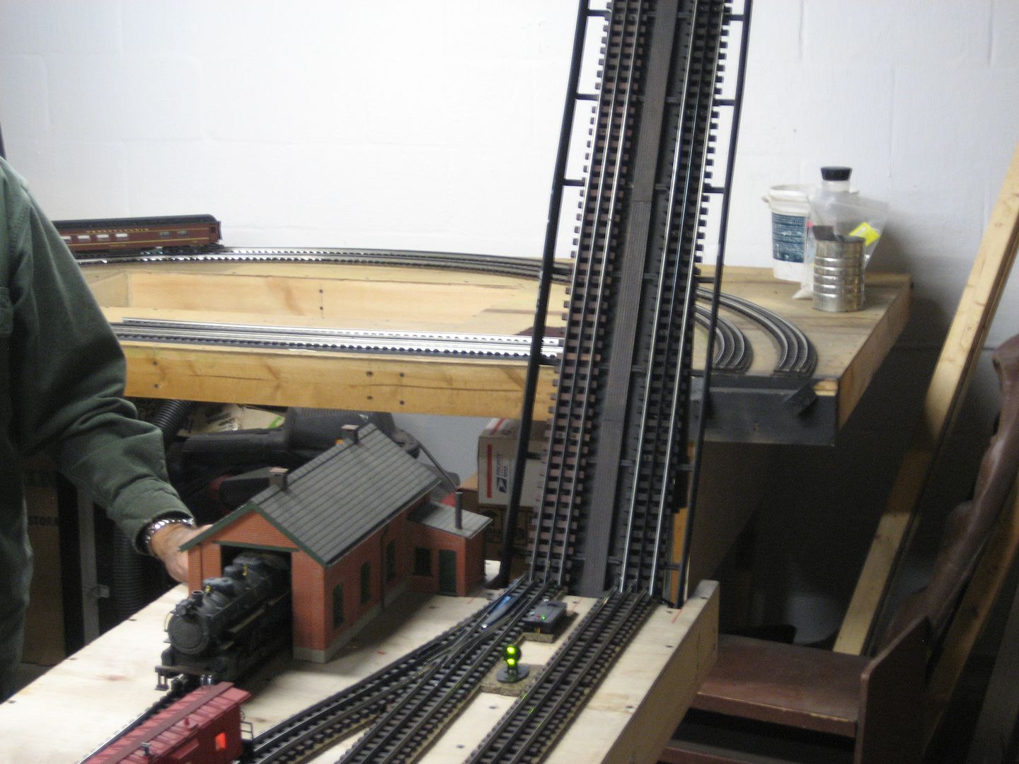
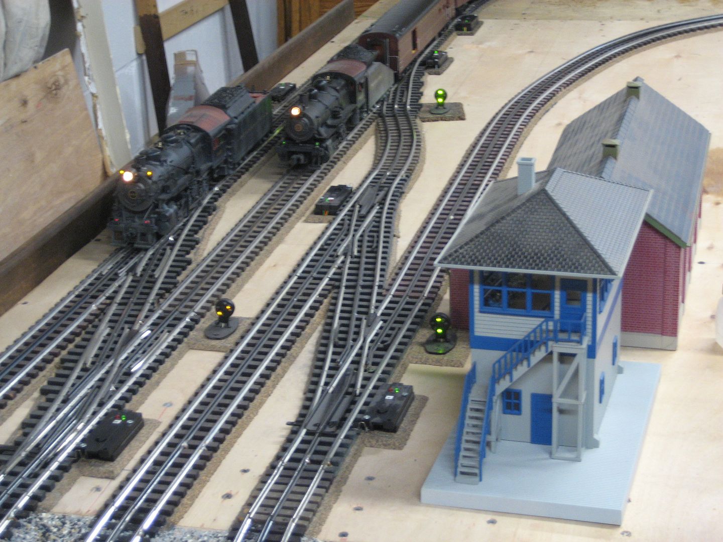
This is not Fastrack.  Gargrave and Ross switches, Gargraves track.   The dwarf lights are activated by DZ 1008 relays associated with DZ 1000 switch motors.

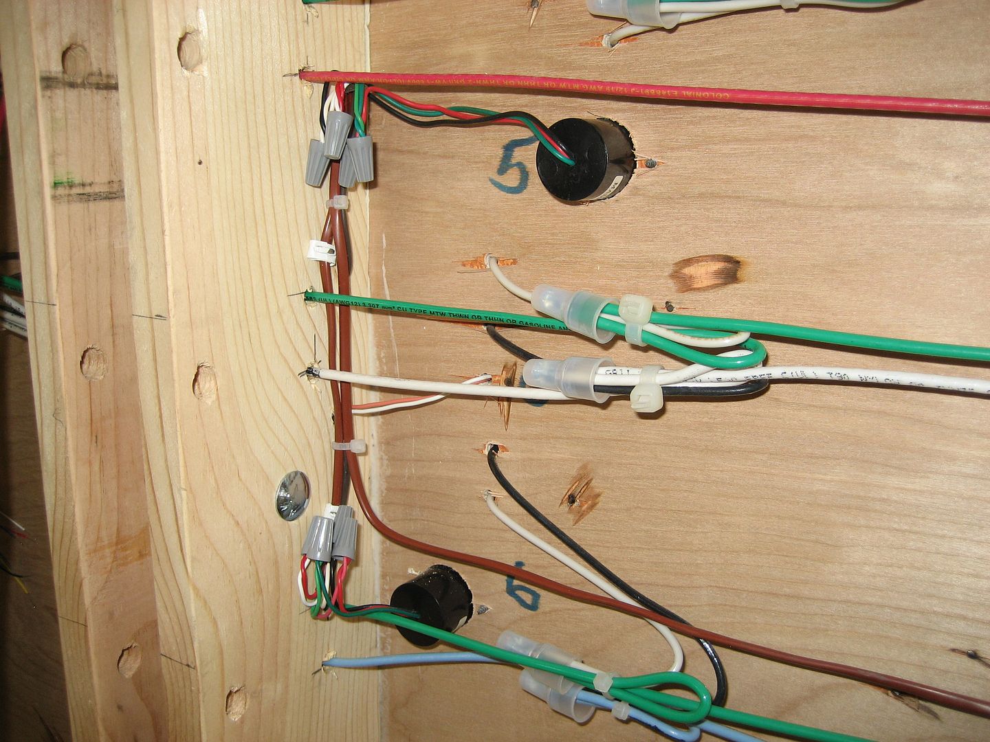
Dwarf light (5) and (6) wired.

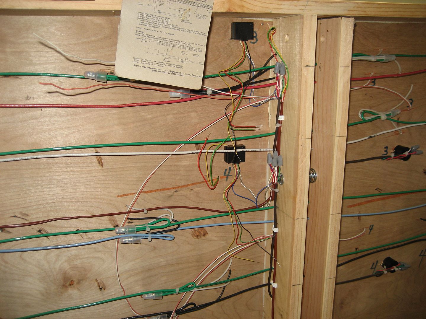
DZ 1008 relay mounted under the table.   Square black boxes marked (3) and (4) that power dwarf light (3) and (4) also pictured.


Last edited by Mike CT
gunrunnerjohn posted:

Why are you removing the track pins?  At the ends of the insulated rail section, you just chop the rail with a Dremel cutoff wheel.

Still can make contact even if you cut the pin off. I usually take the pin out and file the rail down a little bit or use a Dremel to grind it down a bit so there's a decisive Gap between the rails. No risk of electrical contact.

Tfabrizio posted:

Thanks for all of the replies! My dwarf signals are MPC era ones. 

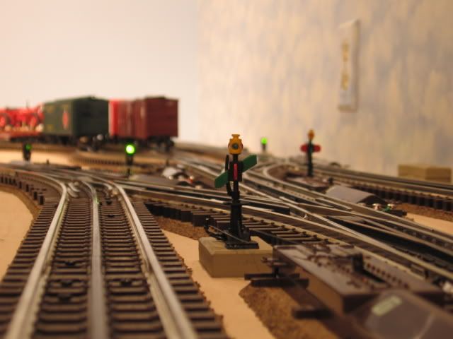
The dwarf lights I pictured above, are also MPC era.   A relay may be required.  IMO. Dwarf lights can be associated with switch position. (green) through and (red) out, as wired above.  I have Atlas dwarf lights on my layout, a bit different they are also wired to the switch motors. 

Another small stand Switch indicator.  These indicators are mechanically connected to the Atlas switch motors and turn when the switch motor is thrown.   There is a small light in the yellow head, unfortunately, wired for 12 volts, was a bit much, and replacement is difficult.


Last edited by Mike CT

if you don't want to modify track, the 5" 6-12060 has cuts in the rails and jumper wires underneath that you can remove to create isolated rails. Any track in between two of them will be the trigger track.

The video of the modification is not that difficult, as you can see. I prefer removing the pins. Then, it can be returned to a regular track again if needed. A curve can be used, too.

I would recommend powering the signals from the accessory terminal of the transformer. Then, use the outside rail to connect the common and light them when a train occupies the trigger section.

Some automotive stores carry .110 female quick disconnect terminals (crimp) that fit the FasTrack tabs underneath. If not one near you, you can find them on eBay. Soldering is the other option.

Moonman posted:

if you don't want to modify track, the 5" 6-12060 has cuts in the rails and jumper wires underneath that you can remove to create isolated rails. Any track in between two of them will be the trigger track.

The video of the modification is not that difficult, as you can see. I prefer removing the pins. Then, it can be returned to a regular track again if needed. A curve can be used, too.

I would recommend powering the signals from the accessory terminal of the transformer. Then, use the outside rail to connect the common and light them when a train occupies the trigger section.

Some automotive stores carry .110 female quick disconnect terminals (crimp) that fit the FasTrack tabs underneath. If not one near you, you can find them on eBay. Soldering is the other option.
Thanks! One more question, since the dwarf signal is not just an on/off accessory, how does the insulated track work? I can understand the concept of power being applied once the train rolls on to the insulated section, but I can't wrap my mind around how the light will change from red to green. 

Sorry for the newbie questions!

Last edited by Tfabrizio

Add Reply

Post
×
×
×
×
Link copied to your clipboard.
×
×