on my STD, I think it would look cool, with alternating  lights in boiler front,  392E, and 400E, ,,thru the celluloid,,

if I could find one of those hats with flashing lights I could use that,

need circuit for LEDS,  will 1 capacitor do it?, I know it works by turning on and off,

thanks,,,


Original Post

Replies sorted oldest to newest

Miniatronics makes a dual, alternating flasher.  I think it works with incandescent bulbs, but you could use LEDs if you add the right resistors.  I bought mine at my local hobby shop.  It was about $15.  I use it for a lighted Marx crossing buck. The biggest problem I had was converting one of the lights to not use a common return.  This wouldn't be an issue for your application.

George

Last edited by George S
gunrunnerjohn posted:

You shouldn't have to pay $15 for a alternating flasher!

Well, I didn't feel like building my own this time.  It may have been a little less than that.  However, I paid $25 for a Circuitron one that didn't have any protection on the transistors and blew out when I accidentally used a screw base, LED bulb.  I was able to fix it once, by replacing the bad transistor, but it blew again for some reason.

thanks,  cjack,

john thanks,   I did flasher search  saw the 555, circuit,  what do you think is better,  using 555, or your other diagram,,yes I want the fade out,  so they don't go all the way out,  of coarse putting an adjustable  resistor in I can set any flash,

whats the volts on the LEDS,

thanks,,


The fadeout is kinda' cool, that would look more like incandescent lighting.  LED's use from 1.5V (red/green) to around 3V (white/blue) to operate.  Obviously, the circuit needs some headroom to operate.  I'd try assembling the transistor circuit on a breadboard and tinker with voltages and resistor values.  I've seen a similar circuit working, it does have a neat look to it.

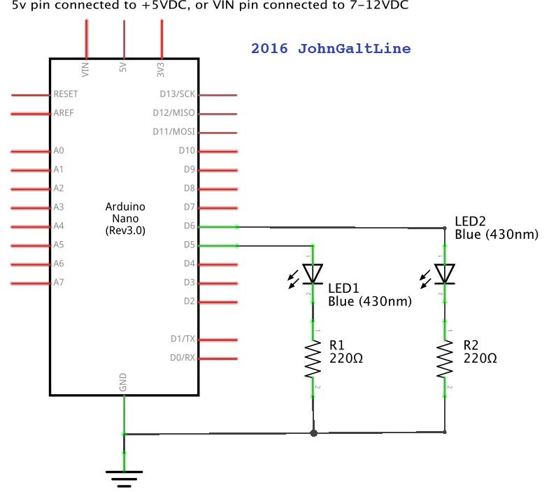
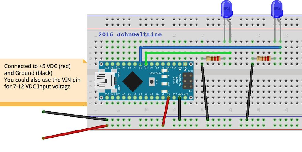
I'll throw this one out there as well.  It is dead simple as far as the actual circuit; Vcc(5-12VDC), Ground, a pair of 220 Ohm resistors connected from ground to the LEDs, and a pair of wires from the high side of the LEDs to an Arduino-type micro-controller.  Total cost is under $2.50 in parts.  Depending on what sort of electronics is in the engine, it may also be pretty simple to add rule17 lighting and cab light that goes off when the engine is moving for just a few cents more.  

This is just a quick and dirty version of the code, that alternates the LEDs, fading them on and off.  well not quite off, I set it to go dim but not quite turn all the way off.  

Also I only had blue LEDs on hand, but white ones usually take the same voltage and current to work.  

int Led1 = 5; // Set LED 1 Pin
int Led2 = 6; // Set LED 1 Pin
int brightnessOne = 5; // Set LED1 start brightness
int brightnessTwo = 250; // Set LED2 start brightness
int fadeAmount = 5; // how much to fade the LED by each cycle
int onTime = 250; // Time to hold at each end of fade (milliseconds)

void setup() {
// put your setup code here, to run once:

pinMode(Led1, OUTPUT); //Set LED1 pin as Output
pinMode(Led2, OUTPUT); //Set LED2 pin as Output
}

void loop() {
// put your main code here, to run repeatedly:

// set the brightness of each LED:
analogWrite(Led1, brightnessOne);
analogWrite(Led2, brightnessTwo);

// change the brightness for next time through the loop:
brightnessOne = brightnessOne + fadeAmount; // LED1 advance
brightnessTwo = 256 - brightnessOne; // LED2 advance

// reverse the direction of the fading at the ends of the fade:
if (brightnessOne <= 5 || brightnessOne >= 250) {
fadeAmount = -fadeAmount ;
delay(onTime); // Delay for each end of fade
}

delay(5); // Delay between fade steps
}


JGL

Riki, as per the request, here is a schematic and a breadboard diagram of the flashing circuit I made.  I'm showing an Arduino Nano, however any Arduino will do the job.  So, if you have very limited space you could use a ProMini, although the ProMini requires a separate part to program it, whereas the Nano can be connected to your computer directly with USB.  

One other note, you can adjust a couple things to get the fade and hold to look better to you.  These variables in particular:

int fadeAmount = 5; // how much to fade the LED by each cycle
int onTime = 250; // Time to hold at each end of fade (milliseconds)

fadeAmount adjusts how man PWM steps to jump by on each fade cycle.  This can be set between 1 and 254, though anything higher than 25 doesn't look very good.  smaller numbers make smoother fading, but take longer for the fade to complete.

onTime adjusts how long the LEDs will stay in the full on/off between fade cycles.

Good Luck.  

Schematic img link.

Breadboard img link.

One last note, I marked the voltage for the VIN pin as 7-12 VDC  you can actually use 7-20 VDC, but I recommend against anything over 12VDC.  If you have a 5 VDC source in the engine, I would use that on the 5V pin instead.  If the 5VDC source you have is controlling other electronics, it probably won't need any additional filtering, however if it is only used for lighting or some such you may need to add a pair of capacitors to filter the power source.  Something like a .01uF and a 220uF will probably be more than enough.

Edit:  Oh, also forgot that I again used blue LEDs in the schematic and diagram.  white should work just the same.  I just couldn't see white on a white background very well. 

JGL

Last edited by JohnGaltLine

Add Reply

Post
×
×
×
×
Link copied to your clipboard.
×
×