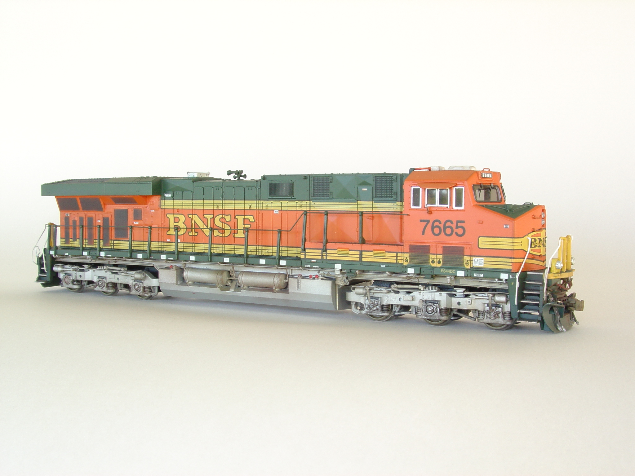
Ok, I've had a chance to look at some better photos. I think what you see there are a series of parts, rather than just one big part.
I'd say the "gas pedal" thing is a sheet metal shield covering something else. That could probably be done with styrene or brass sheet.
There is a moisture drainage valve at the bottom of the end of each tank, it's why the tanks are angled down to that end. That part is available from PSC, #56146. It looks essentially the same as the one you would see on an EMD tank. This is one of my photos from an sd40-2, but the GE looks the same to me.
Also, if you follow this link to the Fallen Flags site, you'll find info (for EMD) on the drainage valve.
The rest is really just piping for the air system, comprised of unions, elbows, and tees, plus the flange where the pipe enters the end of the tank. You can get standard plumbing fittings from PSC, or make your own by wrapping thin styrene around rod or tube to simulate the fittings. The appliances like the filters and moisture traps happen elsewhere, at the ends of the fuel tanks.
I'll see tomorrow if I can get permission to pass along a good photo that should help with modeling this area.
Jim


 </label>


