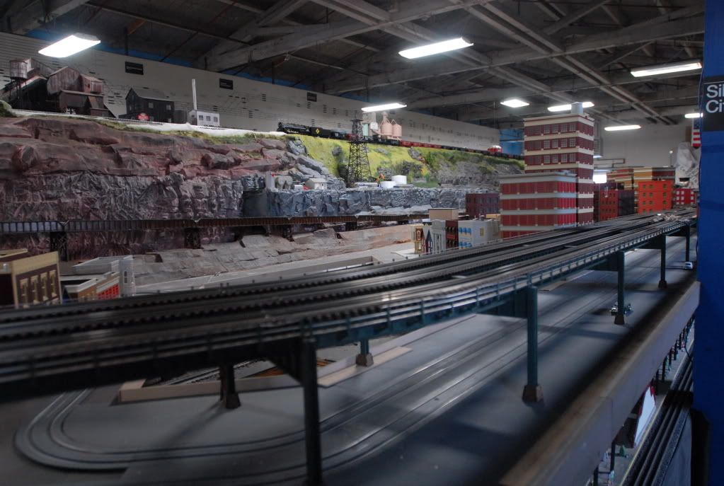
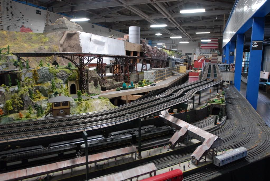
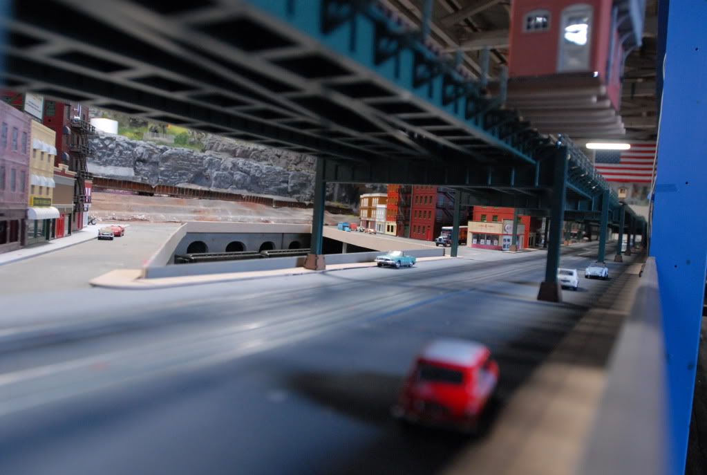
I am in the process of upgrading my "Toy" train layout.  I have two main lines which I set up with Lionel and MTH trestle risers.  I want to convert these to a viaduct and elevated support system.  When I say viaduct I am considering an enclosed berm for the elevation part and a fully supported elevated system for the long flat run.  I want to provide a solid roadbed with 1/2" plywood, roadbed, gravel and weathering.  My eye is on an elevated system complete with girders and fencing.  The pictures below will give you an overview of what I currently have.


Pictures of what you have done, providers and supplies you have used and most importantly your suggestions will be greatly appreciated.  Thank you so much...


Overview - There are two main lines 6" high, running 18' along the back with a third local main running in between on the lower level.


Current, partially built berm.


Elevation 1


Elevation 2

Elecation 3

Elevation 4

Elevation 5

Attachments

Images (5)
  • Elevation 1
  • Elevation 2
  • Elecation 3
  • Elevation 4
  • Elevation 5
Original Post

Replies sorted oldest to newest

Hi Wood:


There are many elevated track systems commercially available. Our friends at the NJHR market one under their Silk City product line. Also Forum member Jim at Bridge Boss sells a system. Also TW Design has offered a system for a number of years.


If you plan on covering the sides with a rock like or wall effect, you might want to consider building your own which is comparably easy. I went that route as the commercial systems were not available at the time I constructed mine.


I also used a 10" height that allows for better viewing. You might want to consider this as well.


Call me or e-mail me if I can be of help.


Hope to see you and your wife soon.

I don't know if this will help or not, but I have a similar situation where one of my main lines runs parallel to, and above the other. In my case, my benchwork was designed for this, by having the two levels. I filled in the space between the levels with styrofoam, then added rocks and scenery to make it look like a mountain wall.


REV


007

0029.1

0043

Attachments

Images (3)
  • 007
  • 0029.1
  • 0043

Bev, Thank you for the view of your impressive layout.  I did not build open girder benchwork and that does pose a bit of a problem.  Not unsurmountable but, it makes a large berm with a tunnel difficult because it would be hard to reach anything that derails.  I like what you did and open girder would make my life much easier. 


John, the silkcity bridge/trestle is exactly what I am looking for.  I will check out their site and see how I can adapt this to my needs. 


Talk about impressive...  That looks like a club layout.  Is it??  If it's yours, I'm coming to visit....   Wow, huge is an understatement...  And, meticulously done....

Alan,  I do like the girder truss and I-beam appearance of the bridge.  They give a very realistic appearance.  Also I am totally into weathering and want to give it some rust, etc.  Eventually, it would be cool to create a work crew section where they are sandblasting and painting a section.


I haven't seen pictures of a rising or lowering elevated section.  I want to begin the initial rise with a berm and then transition to a girder bridge.  I am certain when I talk to Jim he will answer this question.    But does your bridge begin at height or do you rise from a lower level and do you have a picture?

Originally Posted by Wood:


John, the silkcity bridge/trestle is exactly what I am looking for.  I will check out their site and see how I can adapt this to my needs. 


Talk about impressive...  That looks like a club layout.  Is it??  If it's yours, I'm coming to visit....   Wow, huge is an understatement...  And, meticulously done....

Hi Wood, that is the NJHR club layout. we are in Paterson NJ, come down and visit us for a first hand look. the SilkCity website is under construction now. for info please email us or come for a visit.


tie placement e

curved girder 1

Attachments

Images (2)
  • tie placement e
  • curved girder 1

Wood...mine is completely elevated and does not have approaches as you are wanting to model but as Rich states above, that would not be difficult to achieve.  I wanted to model an older "EL" design thus the reason why I went with the open web girder.  I still have to add walkways and railing which hopefully I will get done sometime this year.  You can see the groove and holes along the upper edge of the side girder which will receive the walkway.  In addition, I wanted the black painted look with some rust and weathering streaks here and there which I have not added yet...


Alan

Hi Mike.
 
Alan is correct, you do not need to fasten them. However I have designed into the bottom of each column an anchor point for fastening to your layout deck if desired. They are accessible from the top. There are two different anchor designs available both located at the bottom of each column support. One is fairly simple and the other which is optional provides additional support and enhances the appearance. Let me know of any questions.
thanks.
 
See below a couple of photos showing each type of anchor, the first two are the standard, the 2nd two photos are the optional.


Originally Posted by mike.caruso:

Jim, do your pieces need to be fastened to the surface on which they rest (e.g. screwed in from underneath) or does their weight and gravity keep them securely in place?


- Mike


el column assembly step 5 jpeg

column assy drawing jpeg

misc 030

misc 032

Attachments

Images (4)
  • el column assembly step 5 jpeg
  • column assy drawing jpeg
  • misc 030
  • misc 032
Post
×
×
×
×
Link copied to your clipboard.
×
×