I modified a pre-war tinplate 77 crossing gate for operation with IR detectors and servo motor operation.  https://ogrforum.com/t...tor-and-ir-detectors   I used this circuit from the "IR or Optical Sensors" topic in the electrical forum for relay actuation and time delay.  I added a shunt resistor across the 10uF capacitor to adjust the delay.

The servo motor is controlled by using a 555 timer circuit copied from this topic command-equipped-tie-jector 

I did not need the trigger or power supply portions of the above circuit.

To sum up, I have the IR detection circuit, the 555 PWM circuit and a 5v relay module.  I powered the LED light in the gate from the 5v power to the relay coil.  It seems that the relay module is overkill for this application. I may be applying this same strategy for other accessories, but want to refine it first. My priorities are ease of construction and low cost.  All the parts have been purchased inexpensively from China as many of you have recommended. Here are my questions:

1. Can I use another 2N3904 for the switch across resistor R2?

2. What would be a good way to power the LED? (on when train detected, off when no train detected)

Attachments

Images (3)
  • blobid0
  • blobid1
  • blobid2
Original Post

Replies sorted oldest to newest

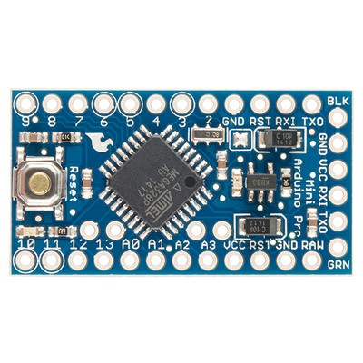
Might I suggest scrapping the whole mess and using a $2 arduino Pro Mini?  one of these boards can control up to 6 servos without additional parts, and your IR sensors can be connected directly to it.   I generally like using discrete components, but with high functioning micro-controlers costing less than a quality toggle switch, it's hard to bother with the components.  You'll need an IR proximity sensor, as these tend to cost less that the individual IR leds and receivers do.  All together you're looking at around $4 in parts ($2 for the Arduino, $0.70 x 2 for the IR modules.) plus the servo and power source.  Not sure if that is low budget enough or not.   You can then use another pin on the arduino to power the led on the gate.  You could even make it flash if you wanted.  

JGL

Mr.Fixit, 

These are the boards I have used, which cost $4.00 at the moment, but are available for that price for pickup 15 minutes from my house. http://www.microcenter.com/pro...duino_Pro_Mini_Board

I've never actually bought an Arduino board from one of the auction site sellers, so I'm not sure that I could recommend one to you.  I've bought almost all of my Arduino boards from Microcenter, and for me the convenience of a local store has outweighed the cost savings.  Even so for a U.S. seller Microcenter has fantastic prices on their brand.  At the moment Pro minis are $4, Uno's are $5, and Mega2560's are just $10.  

When working with a ProMini, the board has the same I/O capabilities as an UNO but it is important to note that it does not have an onboard USB to TTL serial (FTDI) converter, so you will need to buy one of these as well to program the boards.  They are also reasonably prices from online sellers or Microcenter.  

Neither can I recommend a seller for the IR modules I'm afraid.  I tend to do a general search for what I'm looking for, then click the US seller only option to see if I can find it at a reasonable price from one of the many sellers with supplies on hand.  if not I go the china route.  With any such purchase I only buy from sellers with great positive feedback and a clearly written product description, shipping schedule, and a multiple item shipping policy.  The shipping will kill you otherwise.  Many overseas sellers also offer free shipping if you look for them.  I'm afraid I've never had a single bad experience with sellers in china, so I wouldn't know what to look for in a bad seller.  For the most part, however, I use U.S. sellers when the price is reasonably competitive, which it often is for electronic components marketed to the Arduino crowd.  


For your relay modules, I would tend to save them for other projects.  For example, they are very handy if you want to trigger an accessory with the arduino.   

The 3904 can be used as a switch pretty simply, but it is important to note that this is a 'baby' transistor only rated for about 100ma of current.  Plenty for a couple LED's but it can't always replace a relay.  With NPN transistors you generally hook the emitter to ground, Collector to the ground side of the device to be switched, and the base to your low current trigger with a resistor between to limit current.  For logic level stuff about 2.2k ohm usually works, but you should do the math for a proper value if you're not sure.  The 3904 is a pretty weak transistor compared to a 2n2222(500mA) and when buying from china, or in bulk from U.S. sellers, they cost about the same. 

On the subject of programing Arduinos, most things someone would want to do for a simple stand alone device on a train layout are quite simple, and anyone with a basic understanding of how to program should be able to get it done.  For something like this project one could pretty much copy whole chunks of code from the Servo, Blink, and Analog Input examples to get it done, down and dirty.  I don't think the whole thing would be more than two dozen lines of code.  If it is an issue, I'd be happy to help with the code.  

JGL

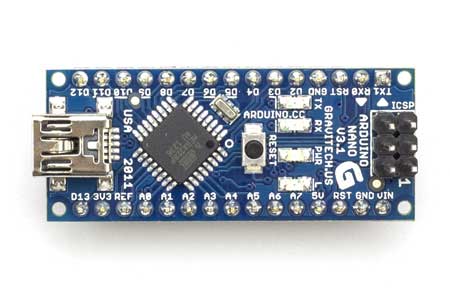
I wasn't aware the Nano's had caught up to the ProMini on price.  The nano is probably a much better choice for the same price.  

One other thing I just remembered that you have to watch for with the ProMini:  They come in two models, a 5 volt and 3.3 volt version.  If you do use a proMini, make sure you use the one with the voltage level best suited to your project.  Most eBay module boards for relays or IR sensors want 5V data lines, but many  things use 3.3V data such as cheap wifi boards. 

JGL

I got some of these IR sensors a while back and they seem to work pretty well from some testing I have done with them. ebay: 121126110685 $0.99 each with $2 shipping (no limit on quantity). I ordered a dozen and the total shipping was $2 for the lot. They were discussed in another thread here somewhere, but I forget which one it was. Seller has a 99.7% rating with over 150,000 transactions, that is pretty good.

I have had NO problems with any of the Asian suppliers on ebay and I have ordered from quite a few of them. I had one bad item a few years ago and they sent me a replacement right away without even asking for the bad one to be returned. It was a different supplier and item than the one listed here. 

I will also second the recommendation for Micro Center if you have one nearby. I happen to have one that's fairly close and they have more of this electronic DIY stuff every time I visit. Their prices are also very good. They have good pricing on computer items as well.

For using up your 555 timers, here is a good site with several model railroad projects using them. Lots of other good circuits here too. http://home.cogeco.ca/~rpaisley4/CircuitIndex.html

Mr Fixit posted:

... just wondering about using up a couple of 555 timers and transistors I have laying around.

To answer your original question the simplest is probably to put an IR phototransistor across R2 in GRJ's circuit in the polarity indicated.  Unlike relay contacts, it is not an ideal switch (0 ohms when on, infinite ohms when off) so let's call it 1K when on (beam hitting it) and 100K when off (no beam).  So R1 and R2 must be adjusted a bit so that R1+R2 sum to the same two resistances yielding the same two PWM values (servo angles).   Whatever trigger signal activated the relay coil would instead drive an IR LED aimed right at the IR phototransistor.  Using a 2N3904 to short R2 can be a little tricky since the voltages across R2 move around which creates transistor biasing issues; the IR LED + phototransistor combo is essentially an optical-isolator which eliminates biasing or ground-reference issues.  Of course all this math can make one's head spin... so if the Arduino approach is in your comfort zone then that's the way to go.

Tie-Jector%20PWM%20Driver

Attachments

Images (1)
  • Tie-Jector%20PWM%20Driver

If you really want to get rid of the 555's, drop me an email and I'll take them off your hands.  The 555 is fantastic  for all things timing and at less than 10 cents a piece they are often the right choice for things like grade crossing flashers.  Back in the day, Radio Shack used to sell these little project books in a series and I know I used the heck out of the one on 555 timer circuits.  there are many fun things you can do if you want to... but the thing is, it's just gotten so much easier to use a $2 arduino than to mess around with figuring out what values all your parts need to be.  

JGL

JohnGaltLine posted:

I wasn't aware the Nano's had caught up to the ProMini on price.  The nano is probably a much better choice for the same price.  

One other thing I just remembered that you have to watch for with the ProMini:  They come in two models, a 5 volt and 3.3 volt version.  If you do use a proMini, make sure you use the one with the voltage level best suited to your project.  Most eBay module boards for relays or IR sensors want 5V data lines, but many  things use 3.3V data such as cheap wifi boards. 

JGL

That's the reason I like them, convenient to use with a ready-made computer interface, and dirt cheap.   You can adapt to 3.3V accessory boards most of the time with a series resistor if you need to incorporate a 3.3V board.  I ran across that with my sound board I'm working on, I use a 5V PIC.  The inputs to the PIC have no issue with the lower voltages, so it was just the outputs that needed the series resistors for the external MP3 board.  0603 resistors are pretty small, not too big a deal.

5V to 3.3V interface

Attachments

Images (1)
  • 5V to 3.3V interface
JohnGaltLine posted:

If you really want to get rid of the 555's, drop me an email and I'll take them off your hands.  The 555 is fantastic  for all things timing and at less than 10 cents a piece they are often the right choice for things like grade crossing flashers.

Don't get rid of your 555s.  Keep them for your Arduino projects.  One reason the 555 endures to this day is its relatively large bipolar driving capability.  By bipolar that's the ability to drive a voltage high or low with >100 mA of current which no Arduino microcontroller chip comes close to.  A 555 chip is a convenient way to boost, buffer, or shift the voltage level of an Arduino output and requires no additional parts.

http://electronicdesign.com/po...pensive-power-driver

So let's do the math....

7 cents delivered to your house...

Untitled

$1.99 (plus tax) and drive to get it...

rs555

Attachments

Images (2)
  • Untitled
  • rs555

wrt inter-connects, for a few dollars more, I suggest

* female-to-female jumper cables, a couple pennies each.  You can obviously cut them in half to solder the flying lead to a custom circuit.  And if not obvious, the ribbon cable can be pulled apart to make a 1-wire, 2-wire, 3-wire, etc. female-female cable.

* if you already have 0.1" gridded circuit boards the female socket strips (break to desired length) can make for tidier daughter-card mounting to the male header strips that you usually install on an Arduino board

Untitled

Since it appears you are capable of experimenting with circuits, if you use the plug-in prototyping boards, another useful item may be the male headers strips that have LONG pins on both sides of the black carrier strip.  Everyone has there favorite technique but I find these LONG-LONG pins useful along with the female-female cables above to connect to a prototyping board as shown below.  Or to easily extend the length of two female-female cables.

I couldn't figure out what they call these LONG-LONG male header strips on eBay so I offer a gold-star to whomever discover the magic search terms to find them.   Thousands of hits for the standard SHORT-LONG strips as included with most Arduino modules.

s-l1600

Attachments

Images (2)
  • s-l1600
  • Untitled
Last edited by stan2004

I would also suggest, if you are new to Arduino, picking up one of the starter kits that come with various sensors, jumper wires and a breadboard.  These little kits will come with some examples and by the time you finish the examples you will have a really good idea of how to program the arduino, and how to connect various devices to it.  

Here's one I've recommended before, again from microcenter, but you can probably find something similar on the bay.  

http://www.microcenter.com/pro...le_Basic_Starter_Kit

I also find it much easier to do my testing with the larger UNO board, then once everything works to my liking, transfer over to a smaller Arduino.  

Also if you are new to Arduino, I highly recommend the tutorial series by Jeremy Blume on youTube.  He starts with the simplest examples and overview, and by the end is into some pretty complex things. He uses nice clear language and is easy to follow and understand.  Part one can be found here: 

https://www.youtube.com/watch?v=fCxzA9_kg6s


On the idea of using 555's to drive outputs, I like it, but I think a 3904 transistor would do the same thing.  Pull up/down resistors handle the sourcing and sinking of current pretty well, as well.  I have occasionally used a pair of inverters in a 7404 to boost a signal, but it has very rarely been needed.  

JGL

Thanks again for all the information, it is exactly what I needed.  I have never had an electronic train project just plain fail in the last 7 or 8 years.  Why?  Mostly because of all the great information on this forum!  Oddly enough, most of my electronic experience is in repair and restoration of radios from the 20's and 30's.  I don't really do much of that anymore - don't have time and got tired of replacing countless capacitors.  I really enjoy tinplate with PS2 (don't have any PS3 yet).  I get the big flashy antique style with modern electronics at the same time - lots of fun.

Add Reply

Post
×
×
×
×
Link copied to your clipboard.
×
×