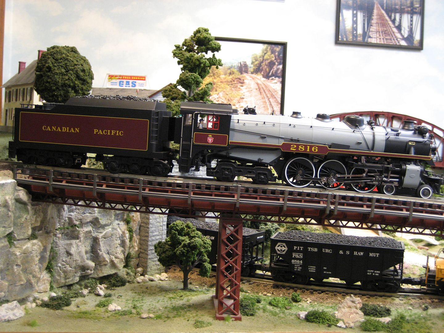
I have a Weaver CP2816 4-6-4 with electronics that died.

I would like to install a Cruise Commander 4.1 and Railsounds
board into it, preferably without lifting the shell as it is not obvious how to do that.
Having a problem getting started.
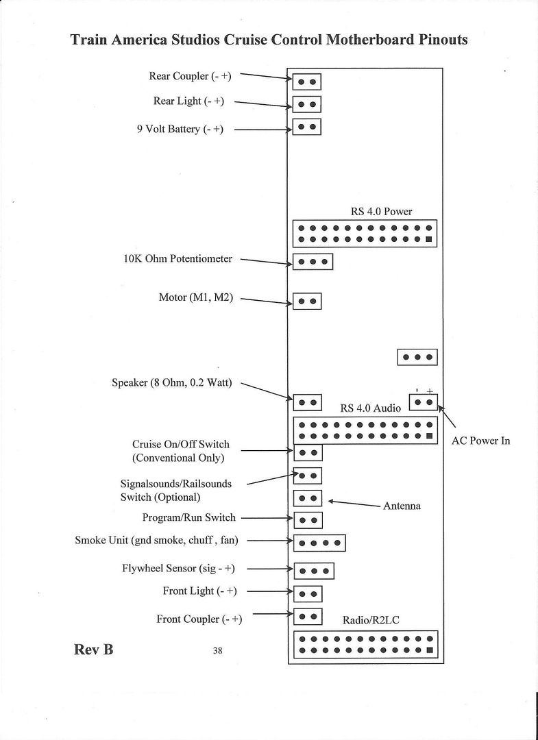
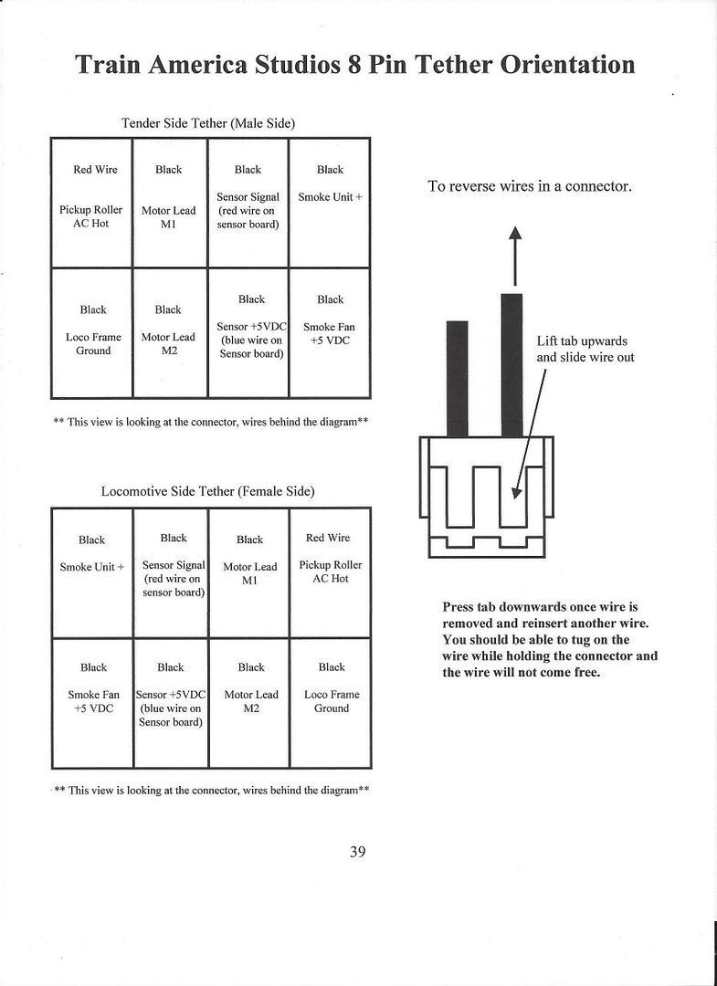
The tether harness from the locomotive has nine wires coming off it. I can ID only two, the AC power leads from the tender pickups.

Pictured is the main board originally installed. On the back is inscribed “2002 Lightning Systems” and “SOW-1-3 11/20/02”

I can trace the wires from the tether to the board but have no idea what the connectors on the board actually are. Without knowing, I can't begin to connect them to an ERR board??

There is no reed switch so a pair of wires on the tether must be reading a tack strip inside the locomotive?2816board

Any ideas as to what this board is and where I could get a wiring guide for it?


Attachments

Images (1)
  • 2816board
Original Post

Replies sorted oldest to newest

Well, I do have an ERR Cruise Commander board on hand, and could procede installing it immediately. But I have no Railsounds board, nor anything other than the original, poor speaker, until I get them ordered. So, it will be a while.

I note from the link John provided that there are three wires on the sensor flywheel terminal labeled "signal - and +. These read the tach strip in the engine I assume. Not sure how they would connect to a Railsounds board?

Will it be necessary to abandon them and install a reed switch and magnet instead?


Thanks John.

This loco has a very troubled history! I posted about it several months ago. Bought new, off ebay, it arrived and would not run properly. It would not move until track voltage was raised to a high level, and then it would take off like a rocket.

Weaver repaired it. Got it back and it ran nicely . . . for two days! Then sound started dropping out and I fiddled with it, reseating boards and whatnot. I never really knew what was ailing it. It has been a shelf queen for 8 months or so.

Not sure what opening the locomotive would accomplish? I just tried two promising looking Phillips screws but, despite having the proper screwdrivers, neither will budge! Any further attempt will strip them!

Also no idea how to restore the EOB to full function . . . or even if it's faulty in the first place.

How would I go about doing that? The condition of the three ancilliary boards that plug into the EOB is also an unknown at this point. Long since having given up on it, the boards have not been given careful handling. There is a board labeled "C08," and two additional boards that carry no distinct labels.

No idea what Weaver did to it that it ran fine for two days after I got it back.

Symptoms yesterday were the same as when I first received it . . . i.e., engine crawls and crawls, barely moving at all, until track power hits a certain very high level and then it takes off at high speed. But now, it's totally silent as well.

Considering all this, it seemed best to gut the electronics and start fresh.

It's a nice engine and I'd really like to see it running. Within reason, cost is no object but there is no one to service it in Canada AFAIK and cross border return shipping a heavy item for repair is crazy expensive.

I cannot buy replacement TAS stuff. I get that. But I gather you're saying converting this thing to ERR Cruise Commander and Railsounds is not a good idea? If not, this thing will be a shelf queen forever. And that makes me sad.

Last edited by Terry Danks

It is a beautiful locomotive I hope you get it running.  EOB is pretty robust/ and worked well in a lot of locomotives. Problems usually existed with the tack-strip coming loose, or the tack reader wiring, both in the loco.  I believe there was a small light on some of the tach reader boards that indicated it was working, that would require opening the engine. Though you can see the tack reader strip/flywheel without removing the shell. It appears, one screw under the front pilot, and two horizontal screws rear cab area attaches the shell to the loco frame.  Something as simple as the tether not set properly, or forced in upside down, could also be an issue.   Read the document that John provided, there is a lot of good information about the set-up. 

Last edited by Mike CT

Mike:

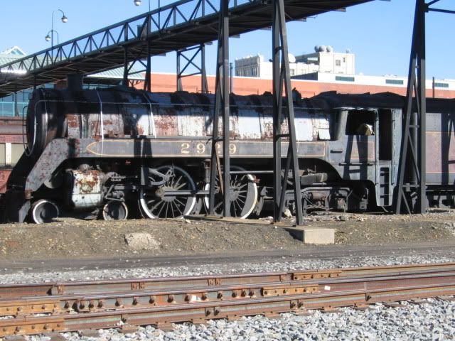
The 2816 is close to my heart as I saw it mouldering in Scranton in 1997 just before it "came home" and was restored. And it is a beautiful model!

John:

Thought I was clear that I have no compunction buying the boards. Already have a Cruise Commander 4.1 board kit on hand with reed switch and magnet. My new Railsounds board went into another locomotive so I need to order another. No problem doing that. That's what I hoped to do, install CC 4.1 and Railsounds with the chuff trigger being a new reed switch, thereby making the tach strip on the motor flywheel redundant.

But I have no idea if there is indeed something wrong lurking under that darned shell that I seem unable to get off. Image attached of screws now basking in a little WD-40 hoping to loosen them. Hope they are indeed the proper screws to get the shell off. Third screw, between the cylinders is no problem. Truth is, I am not sure these are even the proper screws to get the shell off?

No conventianal mode. TMCC. But performance in conventional was the same . . . hardly any motion, then full speed! Yesterday I tested it on fixed 18v track power. First I configured it as a TMCC engine in the DCS remote . . . Then brought it into the active engine list and began rotating the thumb wheel. No motion, then a barely perceptible crawl until finally, as the thumb wheel is turned more and more, from barely moving, it explodes into full 18 v speed??? Yet track power, from the fixed output terminals of the TIU is a constant 18v.

ShellScrewsStumps me.

Attachments

Images (1)
  • ShellScrews

Thanks, Mike and John. Good thing you stopped me as I'd likely have worried those screws until I hacked them up!

Shell is off. I see no sign reading "This is bad here!"

What to look for? Should I be able to rotate that fly wheel with the tach strip by hand or should it be secure and hard to move manually?? I haven't tried yet.ShellOpen

Attachments

Images (1)
  • ShellOpen

If the drive wheels are free, the flywheel should rotate very easily.  I normally test these on rollers.  With the tether connected and power on the engine, you should be able to see the little LED on the tach board turn on and off as you slowly rotate the flywheel.  Check the spacing of the sensor, it should be about the thickness of a dime from the flywheel tape and centered over the tape.


The flywheel should rotate freely as John noted. There should be a small gap (.030"), between the optical sensor and the white and black striped wheel.   Check to be sure (3) wires are attached to the board, I've had them come loose.  Then you would have to follow the three wire system back through the tether connection,  to confirm it is correctly attached to the mother board. 

Last edited by Mike CT
Terry Danks posted:

But I have no idea if there is indeed something wrong lurking under that darned shell that I seem unable to get off.

FWIW, there's very little mechanically that will be a major issue if the motor turns the drive wheels through a full rev freely.  You can test the motor with a DC bench supply with the tender tether disconnected.  It should only take 2-3 volts to run the motor and wheels if they're suspended, and you can also observe if there is any binding,  I just crank the voltage down until it's barely running, any binding is very obvious at that point.  Usually, any binding turns out to be something in the drive rods.

I'm foggy on one thing about this.  I've never run any of these TMCC controlled units/locos with variable voltage.  It was always 18 volts on/off to the track.  My understanding was, they would operate conventional, but what is different about variable voltage to these electronics??  From what's posted, Terry appears to be applying variable voltage.  Does he have a cab 1 control??   There are several adjustments that can be done with the Cab 1, via the instructions posted.


Well, here I am again on my "other sick engine" thread.

To clear things a little. My track voltage is a constant 18 v from a DCS TIU Fixed Voltage output. So, when I say I "raised the track voltage," that was wrong!  What I did was rotate the thumbwheel on the DCS remote to make the engine go faster! It is NOT being run conventionally! (Yes, I have done so in the past . . . with the same problem, but that is not how it's being tested now.) I do not have a CAB-1. My CAB-2 is broken and unlikely to be replaced. I am running the engine (trying to) as TMCC with a DCS system.

I really have abandoned the TAS board and its daughters completely. It is gutted and I have no stomach to reinstall these  boards for any further testing! If they were not defective to begin with, they may well be now as I have made no attempt to ensure they were being treated at all "properly" since essentially giving up on the engine in despair last spring after it died two days after being repaired.

Only hope for my 2816 now is a complete, new, ERR Cruise Commander and Rail Sounds install. The tach strip on the flywheel is now irrelevant. I will use a reed switch/magnet on a tender wheel instead.  So, "heck" with those three wires on the tether! I can ignore them!

Thanks to those here, I have mapped out the 9 wires in the tether from the engine.

Whether I can get these other 6 wires properly connected to the Criuse Commander board, remains to be seen.

What's the worst that can happen? An expensive (VERY!!) engine is already totally broken! I can't "break" it any further! And Weaver is out of business!

Already, problems are apparent. The antenna input to the CC board requires a single slide-on connector. These &^%$#@ nano connectors are Satan's own spawn! So, I have to take this one baby step at a time. How does one attach an antenna lead to an ERR CC board with a one pin connector? 

I am very good at sweat soldering water pipes! The smaller the connection required, the less skill at soldering I have! My trying to solder an antenna lead to a one pin connector on a PCB is a recipe for failure! The board will not survive!

There is nothing obviously wrong "under the hood" of my engine. I had hoped something might be obvious. The sensor "smushed" into the tach strip perhaps? Not so. All seems well.

So, how to proceed? A new ERR CC v.4.1 board is already on hand. Also a reed switch. No RailSounds board as it went into my other ailing engine. I will order another from ERR.


I'd start by taking the tach sensor out as well, clear the decks.

I use a female connector pin on the antenna wire to slip onto the pin on the CC.  The contact in the Lionel 2.54mm connector works really well for this, and I just heatshrink around it to insulate it.

connectorYou probably have some of these connectors, just slide a wire out and use that to connect to the antenna.  You do realize you'll have to solder at some point here, right?


Attachments

Images (1)
  • connector

Hi John!

Man I am keeping you busy!

Regardless of how either of these two "problems" turn out, I really do appreciate your time and assistance. Were I in the US, I'd just send you the things and have you fix 'em and send me the bill! The "other" locomotive has an antenna properly connected to the CC board but I do not have any of these little connectors on hand. I don't know what they are even called? No doubt I can order them if I knew what to call them. Picture of the antenna lead from the "other" ailing engine is attached. What do you call these things so I can order a bunch from DigiKey?

I can solder wires together. But, I am very leery of soldering directly to a PCB. When I see what that Lionel tech was able to do, neatly solder a lead directly to a tiny PCB board, well, the thought of my trying to do that gives me shivers!AntennaLead

Attachments

Images (1)
  • AntennaLead

I installed the CC v4.1 board and finally got my courage up to test 2816 today.

It ran beautifully! I will order a RS board for it today. I had so wanted this engine to run but, after having it fail so soon after coming back from Weaver ( 2 days!!), had given up on it! It's days as a "Shelf Queen" seem at an end!

Thanks, John, Mike and CTR for the guidance! Very much appreciated!


I was interested to learn that 2816 ran the West Island Montreal commuter route during her final active days. I rode those trains daily from 1960 to 1966, so . . .

I, had other things on my mind in those years and paid scant attention to what was pulling my train. Took it all for granted.

But I likely rode behind 2816 a time or two . . .

I'd like to think so.

Add Reply

Post

OGR Publishing, Inc., 1310 Eastside Centre Ct, Ste 6, Mountain Home, AR 72653
800-980-OGRR (6477)
www.ogaugerr.com

×
×
×
×
Link copied to your clipboard.
×
×