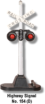
I’m using insulted track instead of those old track activation devices to activate my post war accessories. It’s my assumption that accessories with two plugs are to wired insulated outside rail to one plug and auxiliary accessory power to the other.

But what about accessories with three plugs  such as the Lionel 154 crossing signal. I tried attaching the auxiliary power to the middle post, the outside insulated rail to anther and the third to the main ground for the whole layout. One light burns constantly - likely the o which does not use the insulated outside rail  

what is the correct way of wiring accessories with three plugs and how can those with flashing lights be made to flash?

Any help will be appreciated  

Don

Original Post

Replies sorted oldest to newest

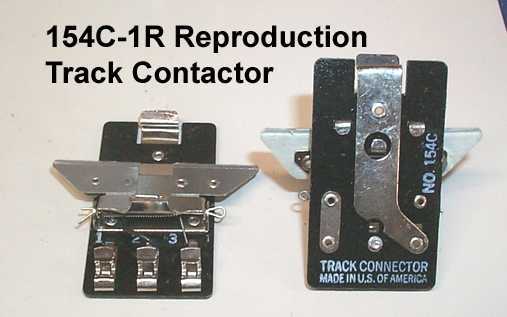
Simple answer, insulated rail as in using insulating pins and then also insulating the outside rail, you would have a tough time making  2 short enough sections to make it flash. The 154C clip on contact trip was how that was originally intended to work.

No. 154 D VariationImage 01 - VTG 1950 Lionel 154 Crossing Signal Instructions Sheet 1950 154-20 2-50 NDEX

Options:

#1 Use the proper 154C clip on for the 154 lights.

#2 replace your old 154 3 terminal light with a modern built in flasher 2 post model. That number is 6-12888

http://www.lionel.com/products...ing-flasher-6-12888/


#3 Buy or build a flasher circuit to place between your insulated rail section and the original 3 post 154.

#4 It's technically possible to build very short insulated rail sections, but just in general, not my first choice since you are making custom track and need extra ties.

https://ogrforum.com/...lock-wiring-question

@ADCX Rob posted:

This is the general method for using insulated track and will work for the 151.

For the 154, you could  do it the Marx way:

Or you could segment the ground rail of any straight or curved section of track by cutting with a Dremel wheel and reassembling the rail with fiber pins... the basics can be found here(Marx discussion, but works with the 154 too...):

Triggering Marx Signals

Here is a good close-up of the original Lionel contactor for reference(from Jeff Kane - The Train Tender):

For fixed voltage, the right post of the signal goes to the transformer instead of the "1" clip on the contactor.

And here is how I do it(the binding post on the right is connected to fixed voltage):

Also, check out this discussion on Realistic Flashing for a 154 Crossing to use the 154 with a regular insulated rail section.

For the 153, you may want to stick with the 153C contactor, a SPDT weight activated switch that switches the red bulb to green & back, until you know how you want to use it, then there are several ways to use insulated rail with relays and additional bulbs.

Last edited by Vernon Barry

An insulated rail acts as an "on-off" switch.  It supplies power as a train passes over the insulated rail.  It can make an accessory with two TERMINALS turn on and off.

An accessory with three TERMINALS such as the 154 signal requires a different approach.  You need to provide a circuit device (there are several available from various manufacturers) that, when triggered by an outside source (such as an insulated rail) provides alternating pulses on two output terminals, which in turn are wired to the two terminals on the 154.

insulated rail ---> flasher circuit --->  left lamp

                                                       --->  right lamp

Thanks. I can’t afford to replace all my 154 crossing lights.  Based on what I have in hand my options are:  

1.  To use the 153 activator which I had hoped to avoid;  (Bu the way Greenbitg’s “Repair and Operating Manual” refers to a 154C connector.  is that different than the 153C?)

2. to use a relay device I have which will cause the lights to flash alternatively for a time that is adjustable; or

3. to use a 153ir that I’m not using elsewhere  

Because trains will be running from both directions I think insulated track will be a necessary part of the solution.  I’ll do some more experimenting to see what works best  

Thanks for your help  

Don Baird

A 153C is not the same as a 154C. Two different model numbers, two different items. (Just so we are all using the same words, the "C" in the model number means "contactor.")

A 153C provides a "transfer" (SPDT) switching arrangement. It has one contact always ON until the weight of a train pushes it down, opening the top contact, and closing the bottom contact.

A 154C has two small, insulated rail segments, each of which connects to one of the signal's two red lamps. They "sort of" emulate the real thing, but it's a compromise.

I'm not sure what you mean by "replacing all my 154 crossing lights." I didn't suggest replacing anything.

If you have many 154 signals on your layout, you can use just one alternating flashing light circuit for the entire layout to operate all of them, and you can have them operate correctly on tracks where the traffic goes both directions. No extra relays; just insulated tracks.

If you or anyone else would like a circuit explanation, let me know either here or privately.

Last edited by Arthur P. Bloom

I'm not sure what you mean by "replacing all my 154 crossing lights." I didn't suggest replacing anything.

If you have many 154 signals on your layout, you can use just one alternating flashing light circuit for the entire layout to operate all of them, and you can have them operate correctly on tracks where the traffic goes both directions. No extra relays; just insulated tracks.

For the record I did, but that was just to give ALL OPTIONS for the user to make an informed choice on what they wanted to do and how complicated the final solution may or may not be.


#2 replace your old 154 3 terminal light with a modern built in flasher 2 post model. That number is 6-12888

http://www.lionel.com/products...ing-flasher-6-12888/


#3 Buy or build a flasher circuit to place between your insulated rail section and the original 3 post 154.


And I think I understand your flasher solution as well with multiple independent crossings. You would just be grounding the signal light base to the sensing insulated rail. All the flasher lights are wired in parallel from the flasher source. Thus, whatever flasher was grounded effectively is on at the time. That's a good idea- provided the flasher circuit was built for the amperage (I know minimal, but still a value that adds up with more lights). I have to admit, I like this idea for a big layout with a bunch of them, just 2 wires between them and the flasher source, just a big daisy chain but all from a single source. Easily manageable and less parts.

Don,

You don't need to use a relay to have your lights flash at the crossing.  Just use a long linked stretch of many (perhaps 10) short insulated rail sections, maybe two inches long each, so that as the train passes over this long stretch, the lights blink as the outer wheels of the cars pass over an insulated rail section connected to nothing, then an insulated rail section connected to your flasher, then an insulated rail section connected to nothing, then an insulated rail section connected to your flasher, etc.   You will need this on both sides of the crossing piece.

Of course, both lights in your crossing flasher will be flashing on and off at the same time, and you will have to have multiple feed wires being connected to the alternating live sections, but it is a cheap solution that works.

Hope this helps.

Mannyrock

Charles P. Bloom

i was not allowed to private message you, but I would like to hear more about circuits  

To provide a little more information, I have a variety of crossing signals, including 5 154s, a couple of wig wag signals with the same three terminal wiring which mystified me, a few of the old Lionel crossing gaurds which could logically be placed with the 154 signals  I also have several of the modern “scale” (smaller) Lionel signals  Because of their Smaller size, I should consider using them at the back of the layout or on the second level  However, I like their realistic appearance  

My locomotives are all postwar, 3 steamers and a heavy Lackawanna  Fairbanks Morse diesel  Rolling stock includes the 64 series box cars I collected as a kid and a lot since  Conventional power provided by a ZW and one or two smaller Lionel transformers  In addition to the two main lines there will be a trolley and a smaller short hall train, each of which will have crossing on level two  

the lower level which I’m finishing now has two mainlines.  Near the front of the layout they run parallel. Two main crossing cross these parallel tracks.   In actual measurements I have one foot of insulated track before and after each crossing with  26 inches of non insulated track between them  A passing train will activate first one signal, and then while the fist is still flashing, activate the second  These crossings are in a busy downtown section of the community.

So, talk to me about circuits  

Don Baird

One more option is to use very thin Copper or Brass Strips

(.010 Thick x 3/4' or 1' wide can be found at any good hobby shop)

These are folded over the rails with a strip of double stick tape on the back side as the insulator. You then solder wires to the strip and run them to the Crossing Signal outside posts. The Center Post on the 154 is for Power and gets picked up from the center rail.

The Insulated strips then become the contacts to trigger the lights. They can be spaced as needed to give very realistic results.

There is a posting from a member who has continuous updates about what he has done on his layout over the past few years. One of the more recent posts was this exact concept.

If you have many 154 signals on your layout, you can use just one alternating flashing light circuit for the entire layout to operate all of them, and you can have them operate correctly on tracks where the traffic goes both directions. No extra relays; just insulated tracks.

If you or anyone else would like a circuit explanation, let me know either here or privately.

this solution would be ideal.  tell me more.

Add Reply

Post
×
×
×
×
Link copied to your clipboard.
×
×