I want to create a walk under double track bridge for an O scale layout. My plan shows an 8 foot span supported at each end by 1.5" x 4.5" boards. The underside bracing would be two 1 x 2's (3/4" x 1.5") the full length of the span. Is this design sufficient that the deck surface will not sag? The aisle width would be no more than six feet, so if necessary the end supports could be moved a foot in on each end leaving the unsupported width about 6 feet instead of eight feet.
Replies sorted oldest to newest
If you run a bead of wood glue the length of each runner under the main platform I would think so. Think of those I-Beams the build buildings out of.
Better to beef up the under-suporting structure, then you can utilize a thinner "roadbed" board/plywood, maybe as little as 1/4" lauan. Maybe 1 X 3 or 1 X 4 for the vertically-oriented support beams, assuming you will be using fir/spruce "construction" lumber. When picking out be sure it is straight, no knots, best if plane-sawed since the grain will be vertical in your structure. Hardwood lumber would offer better/stronger support at the dimensions you've given. Remember also that most lumber from the yard will be "wet" (14-20%) even though it is kiln-dried, and therefore may cup, bow, warp, etc. Best to let it climatize and stabilize somewhat for two weeks or more indoors to see what it is likely to do.
Wally
If you run a bead of wood glue the length of each runner under the main platform I would think so. Think of those I-Beams the build buildings out of.
Good idea on the glue.....probably would have just used screws. I was pretty confident in my design, but my biggest concern was whether the 1 x 2's were sufficient or whether I needed to use 1 x 3's. The basement ceiling is not as high as I would like, so using 1 x 2's would just allow me to walk under it. My taller friends will have to duck no matter what.
I built a screened in room on my deck in the rear of my house. The "roof" is plastic sheeting supported by 1x4s, nominally but really 3/4"x 3 1/2"s of wood. It has an 8' clear span and it hasn't sagged in 7 yrs of Pa. winters with a foot or more of snow on it. If you can, I would use a 1x3(true dimensions).
Better to beef up the under-suporting structure, then you can utilize a thinner "roadbed" board/plywood, maybe as little as 1/4" lauan. Maybe 1 X 3 or 1 X 4 for the vertically-oriented support beams, assuming you will be using fir/spruce "construction" lumber. When picking out be sure it is straight, no knots, best if plane-sawed since the grain will be vertical in your structure. Hardwood lumber would offer better/stronger support at the dimensions you've given. Remember also that most lumber from the yard will be "wet" (14-20%) even though it is kiln-dried, and therefore may cup, bow, warp, etc. Best to let it climatize and stabilize somewhat for two weeks or more indoors to see what it is likely to do.
Wally
I responded to the first member before I read your response. As for the "wet" wood, I have a great deal of lumber that has been in the basement for a couple of years, so the wet factor should not be a problem. Due to low height of my ceiling I need to keep the support beams as small as possible. I was hoping someone might be able to confirm that a 1 x 2 is sufficient. Otherwise you are correct that I may need to go to a 1 x 3 or 1 x 4.
looks Great, just did same thing but only 4 feet in length. I would use a minimum of three 1x3's as the under support. a little extra for a span of this size wouldnt hurt. please post pics once done
Steve
On an 8-foot span, I think you'd get some sagging. However, if this is a doorway, you could "arch" the span by putting a parabolic support underneath which puts them into compression at the ends and better supports the center. You'd have to screw the ends of the 1x2's into the end pier supports.

Is this design sufficient that the deck surface will not sag?
Yes it is. No need to over-engineer the thing. Even with the heaviest O gauge locomotive you're still not asking it to handle a whole lot of weight and it almost certainly won't be sagging.
Do you really want to do a duck under?
Seems its not really all that much more work to build a lift-out section of track.
Jim
Do you really want to do a duck under?
Seems its not really all that much more work to build a lift-out section of track.
I will need it to be a duck under as it will be almost sex feet above the floor.
Jim
stressed skin panels are your best bet for no sag. they are light weight. I made these modules for OCSMR. basically you create a framework similar to a hollow core door and glue and staple 1/4" plywood skins on each side. the blocking on the edge in the picture was for legs, you won't need them. no sag


To Allen Miller and AGHRMatt: I do believe that 1 x 2 boards would be sufficient and I also like the "shape" of the parabolic support. I can do a revision to my drawing and it would meld both ideas together. I would build the supports from 1 x 4 boards. The middle 18" would be the thickness of a 1 x 2. This would give me the height I need to walk under without hitting my head. From each end of the 18", it would curve out to the far left and right ends of the 1 x 4) at a height of 3.5". The curve on each end would give the bridge a nicer look.
On an 8-foot span, I think you'd get some sagging. However, if this is a doorway, you could "arch" the span by putting a parabolic support underneath which puts them into compression at the ends and better supports the center. You'd have to screw the ends of the 1x2's into the end pier supports.

Dear GES
We make a 8 ft bridge and we can make it with either a 6 inch inside clearance of a 9" inside clearance. Attached is one that is made on my home layout. the large (' inside clearance has the added ability to hide a 3/4 pipe on the bottom for extra stiffness or if you want it a smooth surface it can be boxed and a duck or a LIFT OUT IS ALSO BETTER!
Attachments
I built this a few years ago for the same application. Made from curtain rod, extruded aluminum shapes and Erector girders. Sits about 6.5' above the floor and can handle the weight of anything I might be running. Exactly 8' span too.
Bruce
Hello
I would make it like this if using wood ,
I would be using 5 or 7 ply Grade " A " plywood ,cabinet grade.
so you can cut true sizes and not have to worry about finding 1 x 2 or 1 x 3 ,
that were any good.
This would take care of any trouble of warping , checking etc
if you has been looking a wood lately ,all I see is prime grade prices for number 2 wood.
Or just make it out of steel like BRWESTER 's
Which I really like a whole lot
I bet if you replaced the 1x2 with 1x4 and cut it to a parabolic shape (leaving 2" of thickness at the center) like Matt's photo it would work fine (no compression, but the added thickness would most likely do what you want), just make sure you buy straight lumber then glue & screw together.
An 8' bridge will have some weight to it, but you could make it a lift out bridge if wanted.
I like the idea of making it out of aluminum, if you had a place to buy it. Maybe some 3/8" diameter rods or tubing curved into a parabolic shape screwed to some 1" angles, of course you'd have to get the bend done unless you had a way of doing it yourself. I only have about a 4 foot gap I need to make a bridge for, this may be what I use.
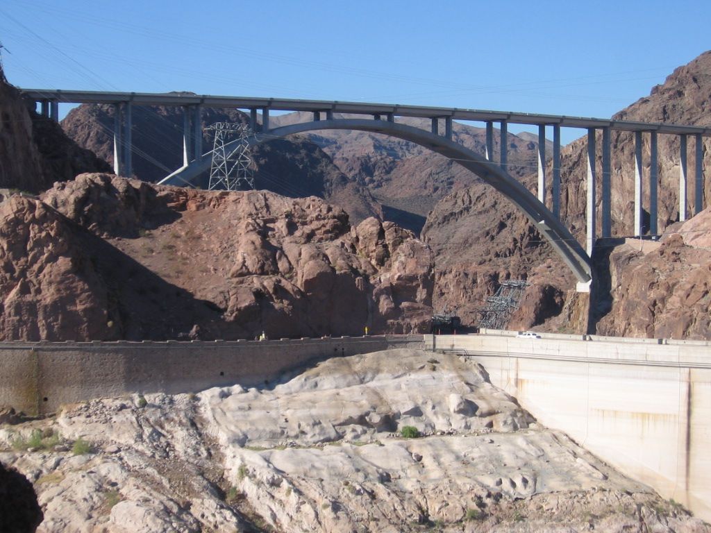
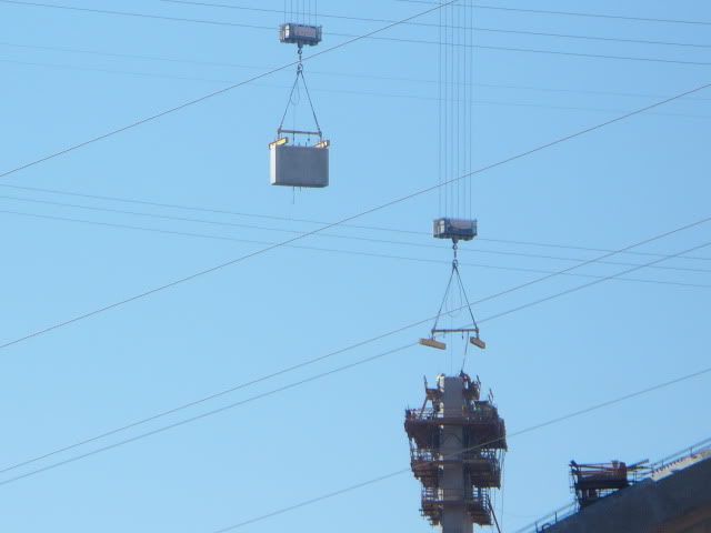
Interesting. ![]() The arched span seems to be an adaptable design to most any length. The O'Callaghan Tillman bridge across the Colorado river at the Hoover Dam is an arch structure, but cable stays were used during the construction. Apparently adding superstructure and cables adds a lot of strength.
The arched span seems to be an adaptable design to most any length. The O'Callaghan Tillman bridge across the Colorado river at the Hoover Dam is an arch structure, but cable stays were used during the construction. Apparently adding superstructure and cables adds a lot of strength.
During Construction.

2006 picture as the arches start to form. Note the towers and the first of many cable stays until the complete arches are formed.
Great post and photos. I was driving under the arch at the Hoover dam when the bridge was under construction. It was a breathtaking view.
Part of the O'Callaghan Tillman bridge is the observation deck, Dam side. General public can access the observation deck most any time. It is 880 ft above the river.
Recent photo, from the great South West on our way to the Grand Canyon.
O'Callahan Tillman bridge observation deck.
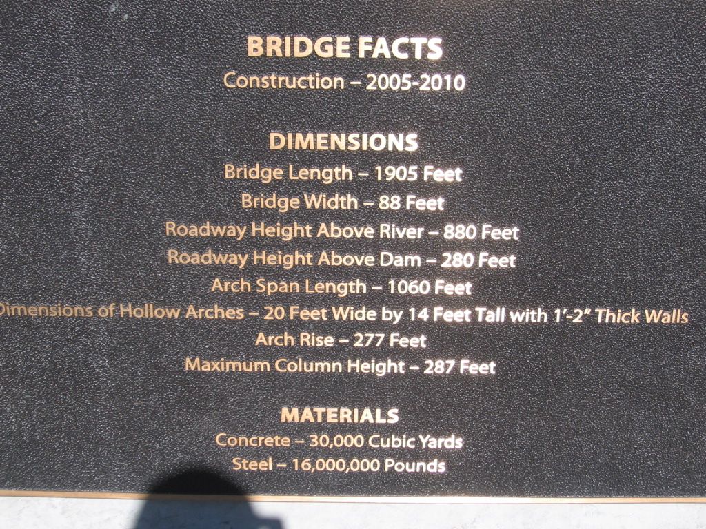
Information about the bridge structure. Scale it to 1/48. 1905ft./48 = 39.7 ft. IMO makes 8ft seem relatively simple. ![]()

I did a diagram revising my original plan and wanted to send it here. Below is the screen I am getting after I try to attach the picture. It states it is uploading, but the message never changes. The file is only 111KB. What am I doing wrong? Thanks.
You can upload photos, videos, audio and files. Please note that there is a file size limit of 100 MB.
Name | Size | Status | |
|---|---|---|---|
No Files Uploaded | |||
bridge 2.jpg | Uploading... | ||


