
Replies sorted oldest to newest

Use the color code to determine which wire is what. The C wire would go to NO on the 153IR. The S on the NC. The last wire would go to ACC PWR

Mainline, like a block signal application: That would have green on and red when the 153IR is triggered until a train clears the IR. Then back to green

I don't think that you will cook anything.

To be certain, use a voltmeter and check the output on the activator box. if it's low voltage or DC, then you would have to power the 153IR with the same voltage and type using the ACC power input instead of track power.

Tfabrizio posted:

Thanks.... My confusion remains though as to what the black and red wires do.

The dwarf signal comes with 5 wires, but the instructions on the back only show 3 (yellow, blue, and white).

Yes, I noticed that lacking in the instructions also. They would be for power in to the activator box red for hot A  and black for common or U. The question is when you supply, say 14 volts AC to the activator box, does it convert it to low voltage DC to light the led's in the dwarf or just pass through the AC for typical incandescent lamps in the dwarf.

Hook the red and black wires of the activator box to an AC power source and then use a volt meter to determine what is being output to the dwarf.

Call mTH cust service for clarification if you lack a meter


Last edited by Moonman

Well, you had the combo when the green light was on - that's where the switch on the control box would move the power to the red wire when the switch changed from thru to out.

Then you could have transferred that wire combination to the 153IR as I described above.

Harbor freight has inexpensive multi-meters. You really need to have one to play with electric  trains and accessories.

We all have let the smoke out of things and learned the hard way. You don't want to let the magic smoke out of anything electrical. Then, it doesn't work.

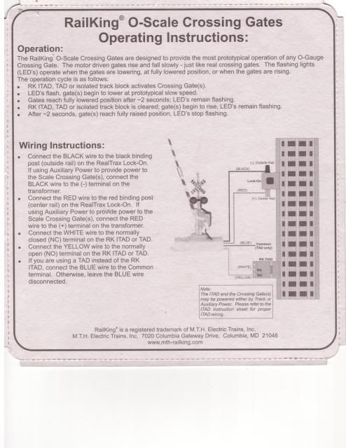
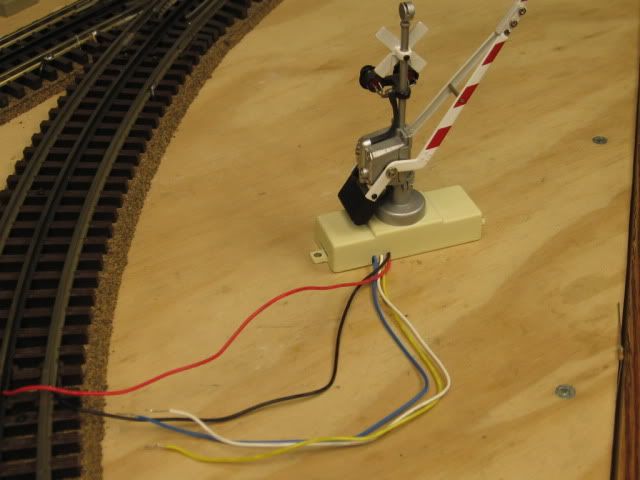
Crossing gate also has (5) wires.   Black and Red are power to the crossing gate.  Blue, Yellow and White are the control wires.

Red center rail, power, Black outside rail common.

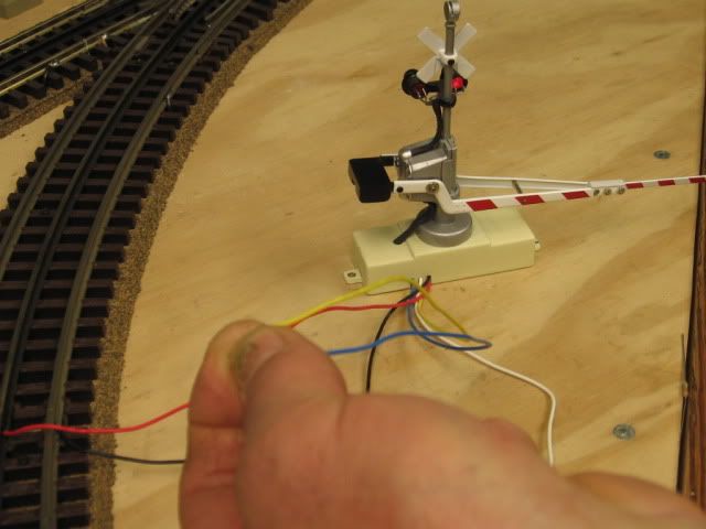
Touch the Blue and Yellow together, the gate should go down, lights flashing, and stay down.

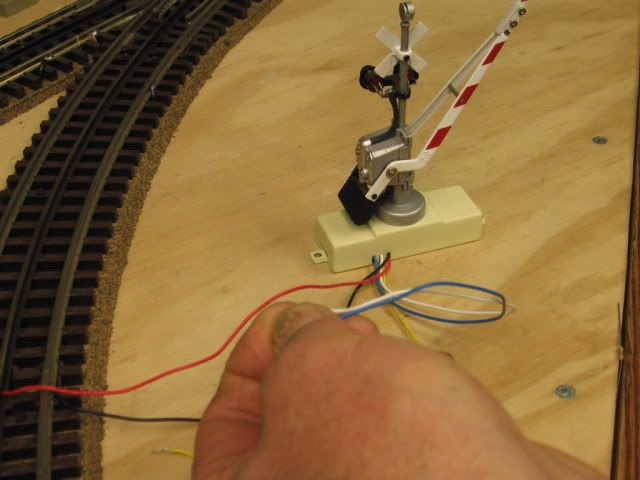
Touch Blue and White together, the gate should go up, lights stop flashing, and stay up.


Dwarf light:  Red and Black, power to the dwarf light.   Blue would be common. 

Blue connected to white would probably be the green light

Blue connected to yellow probably the red light. 

The Dwarf light will require some type of relay, at the least, a normally closed NC normally open NO switch. NC/NO. (Three wires)

Note the instructions on the crossing gate.


Last edited by Mike CT

Add Reply

Post

OGR Publishing, Inc., 1310 Eastside Centre Ct, Ste 6, Mountain Home, AR 72653
800-980-OGRR (6477)
www.ogaugerr.com

×
×
×
×
Link copied to your clipboard.
×
×