A few weeks ago in another thread someone wanted to embed a prime mover model into their diesel.  I poked around the web and found a nice 3D model of an EMD-567 for a princely $200 or so, that was just the model -- not the actual printing of it.  I said I could do better.  Well, here's the result.  It's not really better in the sense that it's an EMD-567.  But my version didn't cost near $200 to print either ($60 range).  But to be fair, it's not a scale EMD-567 with all the details like the model I found -- that I now realize would take some work and scale measurements which I don't have handy.  

Instead what I came up is more like my impression of a diesel engine's prime mover after staring at a gazillion pictures of them on the web.

I first created the model with Tinkercad which is a free online CAD tool.  I guessed at dimensions based on photos and with an eye towards getting the printed model to fit into a dummy SD-40 I have...  so it's about 5" long and 2.5" high and say 1" wide.  (my photos lack a scale.)  I printed this at Shapeways and it just came today in their "default" plastic.   It's grainy looking in the photos but this is less prevalent in real life.

It's also mostly hollow to bring down the print costs.    Next up, I'd like to try a little spray paint...


Attachments

Images (3)
  • mceclip0
  • mceclip1
  • mceclip2
Original Post

Replies sorted oldest to newest

I can do that.  This is a just a prototype.  I'd like to add more things to it to make it look more, well even more engine-y.  I'd like to make a scale 567 based on the real thing too, or any other series of engine.

I plan on printing another soon based on Shapeways pilot program with the new HP printers which they seem excited about.

Ok this is my initial attempt to make it available ... needs some work I think to make it a little clearer as to exactly what it is, the scale should be in the title for one...

https://www.shapeways.com/prod...-1?optionId=63154803

Can you see it?

I didn't open a shop shop I don't think.  The price I see is the same for what I paid less shipping.  (I tried hard to get it below $50 by hollowing much of it out, but didn't quite get there.)

I didn't set it to customizable yet either.  However I can make some changes.  I think 2 exhaust stacks would make sense for some engines. 

It could also be longer, shorter, narrower, etc...

It maybe took 10 - 30 hrs.  But I didn't really add it up.  Tinkercad is very easy to use but isn't really suited to the problem -- to me at least.    It's adding or subtracting geometric shapes.  It amazing what one can do there really but precisely measured scale things, especially tiny things like bolts and nuts, seem somewhat out of reach.   Of course the printers themselves don't necessarily do all the detail either -- except in some cases for quite a bit money.

So Tinkercad is free and you use the browser Chrome.  Works amazingly well for free.

But I'm looking to trying something else for CAD -- the "next step up" -- to eventually try for something more like the real thing.    I'll need to find either scale drawings or make some based on a static display somewhere that I can take a tape measure to.

I painted it with some spray paint and then removing a few screws, followed by some gentle prying -- the entire shell and cab more or less came apart in my hands.  I pushed the cab back together and set the engine atop the frame and wheel assembly about where it should be and ended up with this which I kinda like:

The main part of the shell is on a flat car behind this and I've small crane to look the part -- but that pic is blurry -- and it looks better in real life than in the pic for some reason.

Now I suppose the question is what to do next.   I've more or less ruled out cutting up the shell to get open doors.  Instead I'm thinking about making a printed replica... even a boxy one to experiment with might not be too difficult and I can print it with openings already in place...

Or I could take a crack at a better engine model, the cab interior, or ...

Attachments

Images (1)
  • mceclip0
AlanRail posted:

maybe one of the manufacturers will take notice and add PMs over the electronics with opening side panels 

Having been inside a few locomotives, I highly doubt the current or near future electronics are small enough to be covered by the PM.  Most barely fit in the shell now. 

Pretty nice work there Severn! A cool concept for sure.  Looking forward to see where it goes.

Last edited by MartyE

Just to answer a few or make comment.  The engine isn't really a 567.  It's just me looking at photos of 567s and related and trying to put what I see into a CAD program (Tinkercad -- see website of the same name) -- no measurements, nothing -- just eye-balling it.  Tinkercad is very simple -- you either add or subtract geometric shapes.  It surprising what you can do with that but after umpteen of these operations -- it gets a bit hairy.

So I'm working on upgrading so I can run either sketchup or perhaps one of the adobe "entry level" auto cad based tool sets -- but I'm not there yet.  These should allow for more control of the desired model.  If I do that, I've the interest in making the engine compartment more realistic than what I've done & would probably -- since this is the SD-40 model and it's only dummy I own at the moment -- try to go more prototypical and change up to its engine model also.

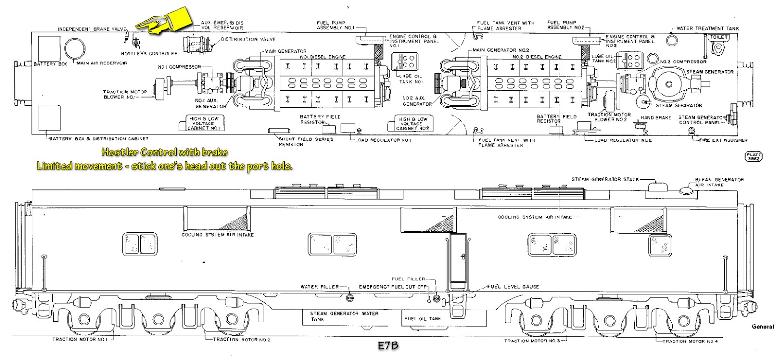
Along those lines:  I'm having some difficulty finding good info in this area.   But I found this last night which seems useful.   Not the operational aspects of it, which is interesting -- but the diagram.

https://www.kirara.co.uk/info/...erator%27s%20Manual/


 I think this is great. Having a few around engine repair houses would look good on the layout.

I could imagine looking in the windows or a roof section that's removed, and seeing engines in various stages of repair or upgrades.

I think the big manufacturer's could offer higher detailed ones than in the past for this use. Maybe seeing this post will at least create excitement.

I bought several Cat diesels on flats for my G scale. There are very high priced ones out there, just to be used inside of a building that may not be seen too clearly. Maybe mixing them up inside and out will give the illusion that they are all higher detailed?

My original intent on this was to make it, print it -- not spend a lot,  cut my dummy engine out and mount the model inside.  I figured the occluded and darkened view of it meant it wouldn't need a lot of detail...

I really didn't consider anything else and went for something simple with fairly low detail.   I also wanted to get the thing printed for under $50... well I came close at least.

But I'm thinking now to try for a better version and I lost interest in cutting up my dummy engine's shell  (I figure I can just print one at some pt, with the doors open).

So I've upgraded to another kind of CAD and I'm hunting around for source material for the engine and related things on it -- to give more realism a go...  (if anyone has any ?)

Beyond that, the models could be scaled to any other scale also... to a point it's a flip of a button.

However larger models might need to be split into several pieces to fit the printers, and of course costs would rise due to more plastic being used, etc...

The current issue of Model Railroader magazine has an article about the 3D printing of an HO model of the Union Pacific Station at Kelso, California in the Mojave area.  There is a detailed discussion in the article of how to design and print larger projects.  This sort of activity is just longing for entreprenurial development.  Those who take the time to design Scale structures for 3D printing should offer their creations to printers to sell to a larger market of hobbyists to enjoy.  It would seem to be an easy process to scale computer designs up or down for three dimensional rendering.

Last edited by The Portland Rose
The Portland Rose posted:

The current issue of Model Railroader magazine has an article about the 3D printing of an HO model of the Union Pacific Station at Kelso, California in the Mojave area.  There is a detailed discussion in the article of how to design and print larger projects.  This sort of activity is just longing for entreprenurial development.  Those who take the time to design Scale structures for 3D printing should offer their creations to printers to sell to a larger market of hobbyists to enjoy.  It would seem to be an easy process to scale computer designs up or down for three dimensional rendering.

Is that the July or August issue?

I'm hoping the prices come down on the printed pieces.  It's not that much plastic.  But it seems to take a few days to print.  They've got some new printers they are testing from HP maybe these will better, cheaper, faster, ... stronger.    Reminds of a silly TV show.  Anyway,  its cool and everything but these things have $0.50 of material in them.

Labor was ... I didn't track it but obviously some time but it's just for fun, so no worries.

I see the above diagrams and they will be helpful.  I've yet to find any truly scale engineering drawings so I'm just going to have to use what measurements like there are above, or I can guess at from photos.  I get that the basic shape is more of Y than the one I did -- and the turbo charger is more swoopy.   I had a hard time with that in Tinkercad... so I'm hoping to improve it.

Also more nuts and bolts and other protrusions....

An SLA print can print with an accuracy of either 50mu or 25mu.

That means approx either .002"  or .001" since in scale as 1/4 = 1 ft or .25"

so at scale 3/8" (1/128') is .008"  However, practically  1/64 is really the smallest detail you can see unaided.

There are limits in size for the printer to physically print that are strong enough to survive. Such as I do not make wall thickness or any other thickness less that .06 which is 1/16" or 3" at scale.


The question about it being hollow -- it's mostly hollow.   I hollowed it out.  The "generator" on the front is hollow and extends into the main box.  The box is mostly hollow.  The large "vent pips" whatever they on top have a hollow portion.  The smoke stack, rectangular piece at the top is hollow.  The large boxes on the front, I believe I put an empty box in each.

The smoke stack is supposed to be hollow into the main compartment but I noticed on my print it's not ... so that's one thing I'd like to fix.

I also guessed at the hollowness because this both easy but difficult to measure with Tinkercad... meaning its possible I could hollow with a better tool.

On tinkercad -- I'm trying sketchup.   If that fails me, I'll try the lowest cheapest preferably free at least for a little while, autocad maybe.

I still like Tinkecad -- it's browser based CAD and worked far better than I expected with a very limited set of operations.  I suspect since Autocad owns it though, it's more of a gateway to other products than anything.

I bought it from someone.  It's in pieces at the moment.  (note: it's a dummy)   Ok wait.  perhaps i misunderstood the original question.  The prime mover itself -- i obviously don't have one.  What I did was use pictures to make something that resembled a prime mover.   And I tried to draw it roughly to scale by measuring the height and width of a prime mover engine down at the B&O real road museum.  My scale estimates are very lax.   But I tried to size it somewhat in the ball park so to speak so it would fit in the model with the shell on -- from memory -- it does.  But I took the model apart to show where it would kinda sit as best as I could tell from pictures.

I had a lot of trouble with the "blower" at top/front of the engine.  In fact I have another version where I create a better blower and some nobbly bits on it -- but I never printed it.

The reality is Tinkercad is not really suited to this kind of CAD -- and I know someone will now say: "Oh yes it is if you..." -- but for me the obvious path was to buy a license for autocad and get serious with some scale drawings if they could be found... 

But I never went there.

Last edited by Severn

I just finished putting this together from some parts that I printed on my 3-d printer. I purchased the cad files from an online website.....  the files where in HO scale and I re-scaled them in my slicer software to o scale.  The coupler is a ho scale coupler I used for scale to my HO friends when I posted the picture in my Facebook feed


20200131_211709

Attachments

Images (1)
  • 20200131_211709
Mike Slater posted:

I just finished putting this together from some parts that I printed on my 3-d printer. I purchased the cad files from an online website.....  the files where in HO scale and I re-scaled them in my slicer software to o scale.  The coupler is a ho scale coupler I used for scale to my HO friends when I posted the picture in my Facebook feed


20200131_211709

That’s great!

How can we obtain either a finished one or the STL file from your hard work?

thanks!

-Mario

Add Reply

Post

OGR Publishing, Inc., 1310 Eastside Centre Ct, Ste 6, Mountain Home, AR 72653
800-980-OGRR (6477)
www.ogaugerr.com

×
×
×
×
Link copied to your clipboard.
×
×