Ross Custom Switches;


I have twenty or so Ross Ready switches W/ DZ-1000 switch machine.

 I intend to use the provided LED push button switch.


What I am asking is if any of the members can post some photos and details of how they did the wiring.


Such as mounting of the switch buttons use of wire terminal blocks just how to do a neat clean and orderly job.


Thank you,

Rudy 

Original Post

Replies sorted oldest to newest

Connect button green to motor green, button yellow to motor yellow. You can join all the reds together, and all the blacks together. Connect red and black to a 14V power source. You can use whatever you want to tidy it up... staples, loom, conduit, etc... 

The only thing I use a terminal strip for is the red and black, so that the power supply is disconnectable.

Make sure red goes to transformer Hot and Black to transformer Common. If you reverse them you won't be able to wire the turnouts for automatic non-derailing operation.


I also strongly suggest using a separate transformer for DZ1000 motor power. Phase this transformer with the track power transformer, and connect the two transformer's Common terminals, to allow automatic non-derailing operation. 


Susan,


That is a very nice control panel.


Rudy,

All of the folks above gave great advise.


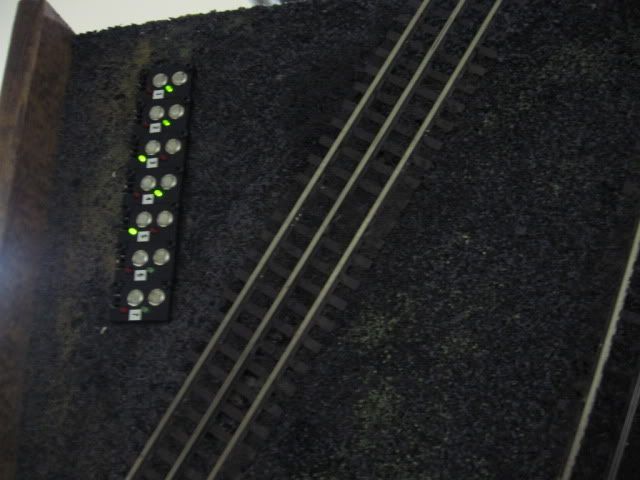
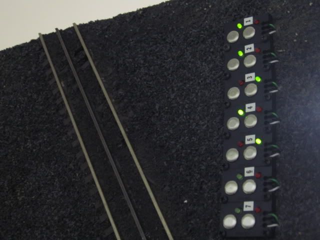
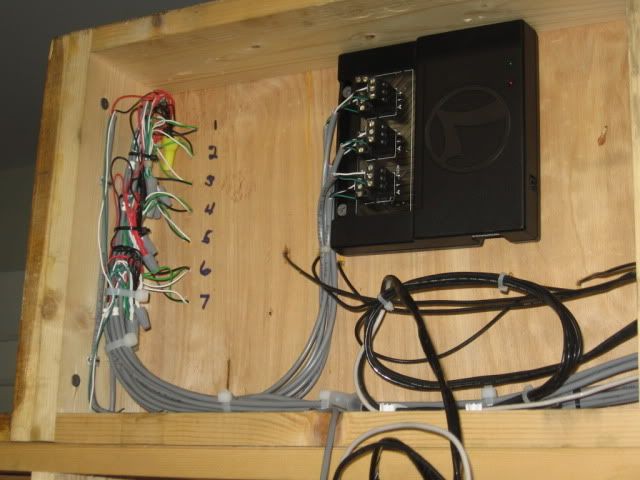
Here are a few pictures of my control panel and the Z 1000 controllers.

I ran a bus line connected to the B or C terminal of a ZW  to all points of the layout for powering the Z1000 switch machines. Terminal strips are connected to the bus in areas where there is a cluster of switch machines. As mentioned above the switch machine red wire will go to the terminal strip / bus.

For making the run back to the control panel for the other two wires I found that using 8 conductor irrigation control cable with 18 AWG solid wires worked the best. Each cable run can be used to wire 4 switches to the controllers in the panel.  Just make sure the green wire on the switch machine ends up connected to the green wire in the controller, and the yellow wire on the switch machine ends up connected to the white wire on the controller. The black wire on the controller goes to your common ground. Since I had over 50 switches to wire I placed terminal strips in the control panel for connecting the black wire from each controller to ground.  The terminal strips in the pictures with the white wires are the ground terminals.


The Control Panel


863_6397

863_6396


Inside the panel.


864_6403

863_6398

863_6400

I used white wire for the color of all comon ground wires on my layout. The lights on the control panel are also grounded to the comon terminals with the white wires.


I hope this helped.

Richard

Attachments

Images (5)
  • 863_6397
  • 863_6396
  • 864_6403
  • 863_6398
  • 863_6400
Last edited by Richard Gonzales

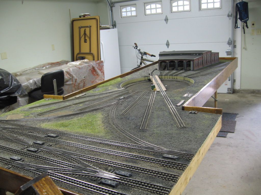
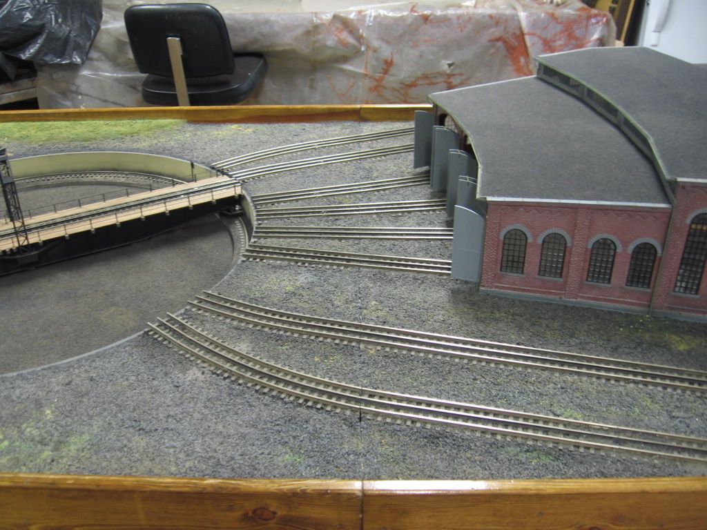
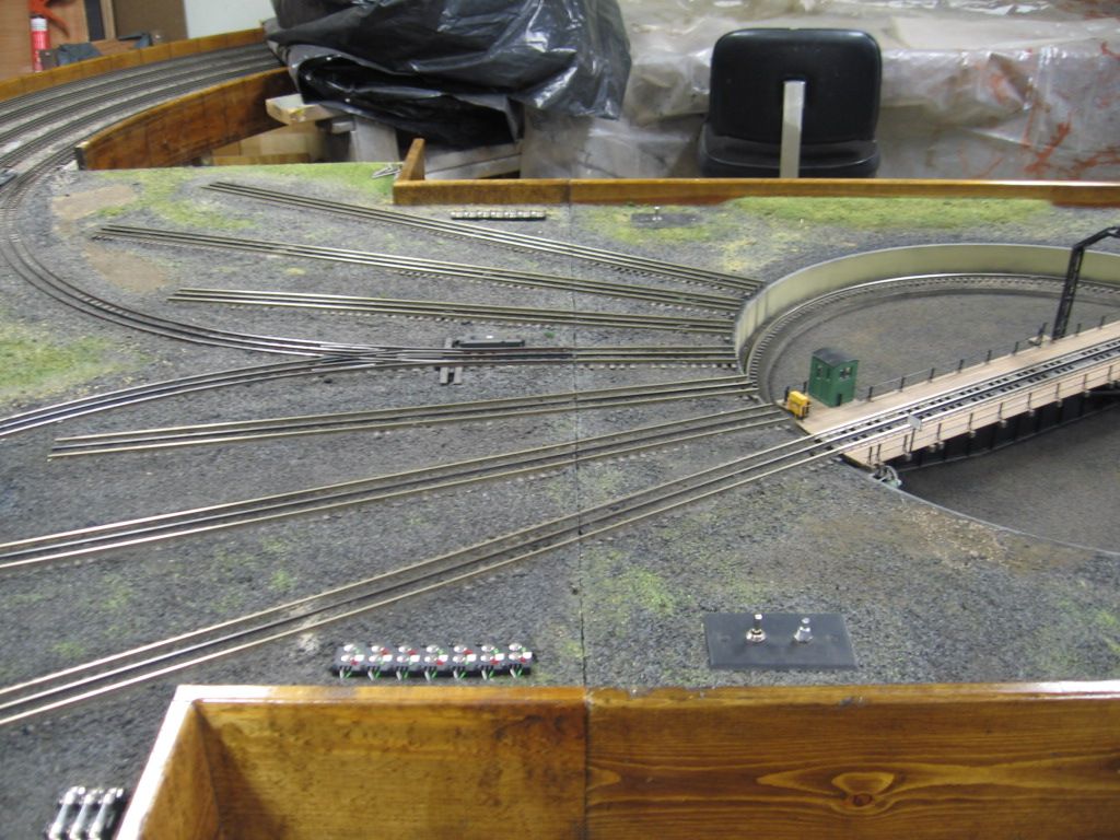
The "Y" module, for the Fort Pitt Highrailer's Turntable has (2) Ross 3way switches. (4) corresponding Ross 101 switches for cross overs.  (2) Ross 101 for TT "Y" access and a Ross "Y" switch.  (14) push buttons, (7 pairs), and TMCC control of (6) switches with a Lionel SC-2.  Automatic non-derail was also wired as part of the project. Click on the underlined phrase to access the picture file.

A video of how it works.

Originally Posted by Mike CT:

Hello Mike,


Very nice workmanship.


your video shows nicely the derailing option.


Thank you,

Rudy 

The "Y" module, for the Fort Pitt Highrailer's Turntable has (2) Ross 3way switches. (4) corresponding Ross 101 switches for cross overs.  (2) Ross 101 for TT "Y" access and a Ross "Y" switch.  (14) push buttons, (7 pairs), and TMCC control of (6) switches with a Lionel SC-2.  Automatic non-derail was also wired as part of the project. Click on the underlined phrase to access the picture file.

A video of how it works.


Originally Posted by Richard Gonzales:

Mike CT,


Very nice engine terminal modules. I wish we had your modules on Casey Jones layout How many modules does it take to build this portion fo the Fort Pitt High Railers modular layout. How big are the modules?  (3) modules  The Tee module is 5ft X 6ft note the 1ft X 4 ft neck.  TT module is 4 ft X 4 ft  and the RH module is also 4 ft x 4 ft.   I don't own the TT modules any more, they belong to another member of the FPHR club.  Tentative plans are for these modules to be part of our display at the TCA spring York, PA  meet this April, White Hall.  

The Bike is a Trek 6500 hy-brid.

Best wishes,

Mike CT 

Richard


Last edited by Mike CT
Post
×
×
×
×
Link copied to your clipboard.
×
×