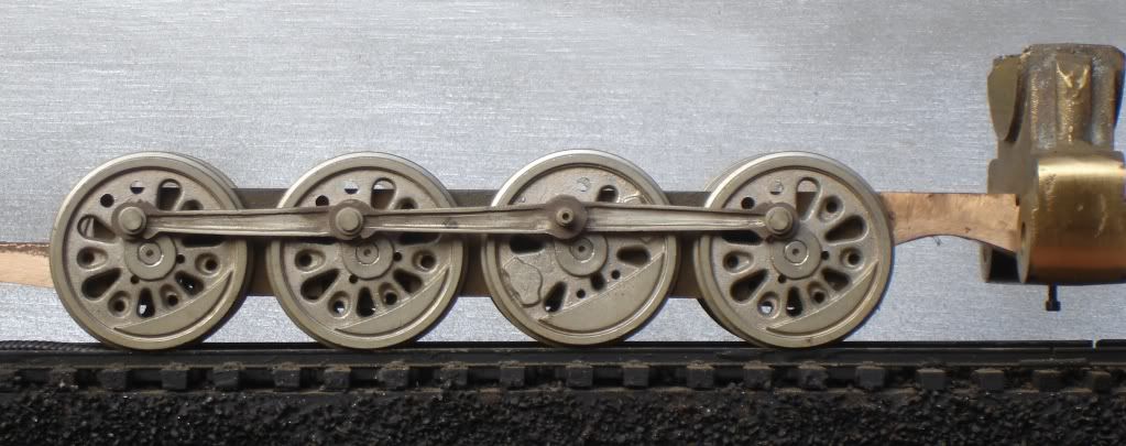
I have a few ideas how to do this.  Interested in how others have made them.  Usually someone has a better idea and something I haven't thought about.


My basic idea is to use brass sheet (thickness?), scribe the rod outline, mark center line/drill for holes, and cut from sheet.  File in the details.


Use thin brass strip (.005) to 'wrap around' entire rod to create the "lip".


The rod bolt holes have to be perfectly centered on the drivers or there will be binding.  Any ideas on how to do this easily?  Preventing binding is my big concern.


After much contemplating, the stock Weaver FEF rods aren't going to do for this project.  FEFs had unique UP design that I want to copy.


Last edited by 86TA355SR
Original Post

Replies sorted oldest to newest

First, check with Bob Stevenson.  I believe he has masters for these rods - not sure.


I made a set of masters over a decade ago - I use a milling cutter to carve the indented area, add the lubrication fittings, then get them cast in nickel silver.  I did masters for most common driver spacing, most with a smooth side and an "I" beam side, so they were reversible.  Most were clevised at the articulating joint.  Stevenson should have all of them.


Drilling rods is a whole 'nother topic.  Note that the critical dimension is the driver center!


Most steam drivers are center-drilled.  I do that to aid in quartering, and use the center holes to get the rod hole spacing correct.  I also will lock a set of drivers at front or back dead center to drill the articulating pin hole in place.


If a set of rods smoothly goes through front and back dead-center, then your locomotive will roll freely IF all drivers are quartered correctly AND all crankpins are exactly the same distance from axle center.

bob2,
Thanks for the photo, those are what I'm looking for.
 
Originally Posted by bob2:

First, check with Bob Stevenson.  I believe he has masters for these rods - not sure.

I remember you stating that in my other thread.  Left a message a few weeks ago but I know he hasn't been in the best health.  Left him another just now.  Hopefully, he has your set and I can buy them: would save me lots of time and effort.  Probably a better product than I can make anyhow.


Drilling rods is a whole 'nother topic.  Note that the critical dimension is the driver center!

   I can use the stock driver center.   For the rods, I'm working with a drill press, scroll saw and hand tools.  Be **** hard to get the rod holes dead center with that stuff.  I don't have any equipment to measure accurately.

I'd like to avoid this if I can. 


I'll take a look at big train's link.  Thanks.

Last edited by 86TA355SR

You're right Ron.  I've noticed that on several different manufacturers.  


I've thought about using my existing rods to measure the rod bolt centers.  Hope to hear back from Bob Stevenson to get a 'copy' of bob2's FEF rods and be done with it.  Like we've said before, sometimes it's a lot easier and worth the money to buy a part than make it!


Here's the Weaver rods compared to the correct rods Bob posted:


IMG_6938

Attachments

Images (1)
  • IMG_6938
Last edited by 86TA355SR

You need:


Drill press ( you already have one) Fifty bucks at Harbor Freight this week.


Dividers


Magnifying glass


Center punches (small and medium). I use a General spring-loaded punch for the first punch.


Appropriate drills, with zero rake angle (easy with a Dremel, and absolutely essential for safety in brass and nickel silver). Use a #50 first.


Round Swiss file


That's it.  Nothing sophisticated.  Dividers are more accurate than a ruler, and even more accurate than using your old rods.


Originally Posted by bob2:

First, check with Bob Stevenson.  I believe he has masters for these rods - not sure.


I made a set of masters over a decade ago - I use a milling cutter to carve the indented area, add the lubrication fittings, then get them cast in nickel silver.  I did masters for most common driver spacing, most with a smooth side and an "I" beam side, so they were reversible.  Most were clevised at the articulating joint.  Stevenson should have all of them.


I can't get in touch with Bob, I've left/sent messages.  I know he had some health issues, anyone know if he's ok?   


Drilling rods is a whole 'nother topic.  Note that the critical dimension is the driver center!


Most steam drivers are center-drilled.  I do that to aid in quartering, and use the center holes to get the rod hole spacing correct.  I also will lock a set of drivers at front or back dead center to drill the articulating pin hole in place.


If a set of rods smoothly goes through front and back dead-center, then your locomotive will roll freely IF all drivers are quartered correctly AND all crankpins are exactly the same distance from axle center.

I need help. No matter what I do, I can't find driver center..How do I do that?


The drive wheels are mounted.


I've used dividers, calipers and just about everything else I can think about to locate dead-center. I'm rewarded with binding after 3/4s of a revolution-I can see the rods are off center and binding on the studs. 


There's a lot of 'play' in the wheel sets/gearbox. Almost a 1/16" right or left.  Changing the gearbox isn't an option.  I may end up using the old rods if I can't figure it out...  


Ideas?  What am I missing here?

Last edited by 86TA355SR

How about a photo?  You can find driver spacing if there are no center holes by finding the interface between axle and driver.  If that is not possible, try to measure from the rim or even the tread.  Of course what you are looking for can only be found on the dead center of the driver.


Aluminum is cheap - practice with some aluminum strips.


Normally, MTH/Lionel/3 rd Rail drivers are properly quartered with matching crankpin distances.  But just in case, check your quartering.  Here's how to do it rough and dirty:


Take your scrap aluminum, and carefully mark and drill one side rod, with holes for all crankpins.  Slip that rod ovet the pins on one side, then rotate them to top or bottom dead center.


Tape or hold them in place, then go to the other side.  Your pins on that sied will be at front or back dead center.  With a straight edge, make sure they are all in a straight line.


If they are, you are halfway home.  The check for crankpin distance is just as simple:


Once you get a rod drilled (aluminum scrap; the same rod you used for the quartering check) run each set of drivers t hrough front and back dead center with that rod in place, and no rod on the other side.  Binding at either extreme will either be incorrect drilling, or  much, much worse, non- matching crankpin distance.


Siderod slop is actually ok - once you go through these steps, open up the rod one drill size, and try it again.  If one or more pins are still binding, open up the rod with a small round Swiss file.  Usethe magnifying glass to see where the pin is binding, and adjust accordingly.


Finally, note that many steamers have equal spacing on drivers.  Most Mikados, a lot of Mountains, almost all Northerns (SP is an exception) and darn near every Pacific and Hudson have equal spacing.  So, when you are using your dividers to see axle spacing distance, do several measurements, including one over all equally spaced drivers, and see if the number you come up with for individual axle spacing divides into the overall spacing.


Wordy, but let me know if this helps?

When I have had to fit a set of side rods to a mechanism that has its drivers in place (not too often), I use a dial caliper to measure between the outside edges of the adjoining axles and subtract the diameter of one axle from the reading on the dial caliper.  This brings you to a measurement that is exactly center to center of the driver crankpins (assuming the crankpins have all been machined at the same distance from the driver centers.


I mount the rod blanks on my milling machine table parallel to the movement of the "X" axis on the table,take up any backlash in the table feed, set the dial on the table feed dial to "0" and using a center drill in the milling machine chuck, I drill a pilot hole in the rod.  Then I move the table with the x axis feed handle to the measurement obtained above and drill the next hole repeating until all of the crankpin holes are spot marked on the rod.


Then the rod can be mounted on a piece of flat scrap wood and the final hole size drilled in the rod.  I recommend making the finished holes about 0.005"larger in diameter that the crankpin diameter.


Joe Foehrkolb

Bob, Ron and Joe,

I appreciate the help, it's simplified this greatly.


I have a side rod that doesn't bind!  Smooth operation throughout the entire rotation. 


Turns out my old dividers moved when measuring the holes, unknown to me at the time (s).  They went in the trash and I took Bob's advice-bought a locking divider set at HF for less than $5!  Made all the difference.  


I scribed a center line, carefully marked each hole using the dividers, center punched, drilled pilot hole with drill press, moved up drill sizes progressively, and it was dead perfect.  I didn't even need the swiss file to clean up the holes!


Here's a picture prior to cutting them out of brass:


IMG_7644


After cutting and filing, need to add fluting:


IMG_7646


Other side Thursday night.

Attachments

Images (2)
  • IMG_7644
  • IMG_7646
Last edited by 86TA355SR
Originally Posted by 86TA355SR:

I have a few ideas how to do this.  Interested in how others have made them.  Usually someone has a better idea and something I haven't thought about.


My basic idea is to use brass sheet (thickness?), scribe the rod outline, mark center line/drill for holes, and cut from sheet.  File in the details.


Use thin brass strip (.005) to 'wrap around' entire rod to create the "lip".


The rod bolt holes have to be perfectly centered on the drivers or there will be binding.  Any ideas on how to do this easily?  Preventing binding is my big concern.


After much contemplating, the stock Weaver FEF rods aren't going to do for this project.  FEFs had unique UP design that I want to copy.


If you have the rods use transfer punches. They work great for getting the exact hole  spacing.


Fluting is tough.  You might find that soldering two wires on the outside, then filing, would be best.


I do them on the end mill, but the work is so tedious that I just do one or two, then have them cast.


Joe is lucky to have good precision machinery, but as you have seen, a careful measurement and center punch, followed by careful drilling in stages, can be done without a really good mill.

I've learned a lot from this project.  Getting better at making stuff and learning how to do things the right way.


I wish I had a nice lathe and precision machinery, but I don't (will some day).  For what I have in the shop, I don't think I could have done better.


I'm going to use Bob's wire/flute idea-much better than what I had in mind.


Will post the other side when done and fluted.  Can't wait!

Joined this discussion late...please forgive me if the following is irrelevant to the OP's needs.


If casting the side rods in a durable metal...brass, nickel silver, etc...is the final and/or preferred option, I'm wondering why creating the master from a material such as sheet/strip styrene or ABS wouldn't be an easier trial-and-error option? 


For example, if  establishing the hole spacing/alignment for smooth running is the primary initial effort, I should think working with, say, 0.060-0.080" thick strips of styrene or ABS would be an easy, low cost (time/money) option.  Spotting the hole centers in plastic stock with a low force center punch/awl, then boring the holes with a center point drill bit (rather than a spot drill bit, preferred over a center point bit for harder materials/metals) should be quick and easy.


Once the spacing/alignment has been established in the basic strip, the rod profile contours can be cut/filed.  fasten the finished rod to a flat backing, create the mold, cast the part(s).


Fluting preferred/required?....Using the rod master completed as above, trace its contour onto a sheet/strip of stock having thickness equal to the depth of the fluting.  Then, carefully cut/file the rectangular spaces for the flutes. (easy to do with a #11 knife blade in thin plastic stock!)  Carefully laminate (solvent weld) the fluted piece to the master.  Then finish file/polish the outer contour of the fluted stock to the main rod. 


FWIW, I made a simple rod (3 axle, no flutes) using ABS strip to make a young lad's HO engine serviceable again many years ago.  Sure, there was some trial/error, but it went fast, was easy to start over, and, although not very durable in the long run, it worked sufficient to get a smile and thank you.  Just reading through the earlier responses, it seemed a logical step to use the effort in plastic as a master for casting a part in metal.


But, since I've never tried this last leap myself, and I have no one....short of a local jeweler, maybe...to do such casting were I to try it, I thought it might be worth sharing as a thought-starter for others.


FWIW, of course, always....


KD


Last edited by dkdkrd

My buddy is a dentist.  He has some stuff that might make that viable - I will check.  But ordinary lost wax molds are vulcanized, so the master has to be metal.  You get 1/2% shrink form the conversion plastic to metal, then another 4% when you make the mold.  Complicated, but doable.  My PA truck sideframes were done that way.

Originally Posted by Ron H:

Aaron, great work. for the fluting you can use square brass wire. Available at hobby shops and Hobby Lobby. Look forward to the finished rods.


Also, you can solder thin correct size washers on the rod ends and file down to perfect shape.


Ron

Ron,

Great tip, I'll hunt some down tonight or over the weekend.  I like simple as you know!


Never thought of the brass washers, what an excellent idea!  


I can't tell you and Bob how much help you've both been.  Thanks 

Originally Posted by bob2:

My buddy is a dentist.  He has some stuff that might make that viable - I will check.  But ordinary lost wax molds are vulcanized, so the master has to be metal.  You get 1/2% shrink form the conversion plastic to metal, then another 4% when you make the mold.  Complicated, but doable.  My PA truck sideframes were done that way.

Ah, yes.....shrinkage....forgot about that nemesis...but have experienced it in making non-functional resin cast parts. 


So, perhaps that's the reason so many imported, 'mass-production' brass engines (thinking HO, especially, here) had segmented and overlapping side rods for multi-axle drivers??  Segmenting, while not at all prototypically accurate but easily disguised in a model, helped to achieve smooth rotation of quartered drivers???  Oh, yes, and segmenting probably also helped with driver alignment/binding issues for operation on sharper radii track curves, come to think of it.


Also, I was suggesting an alternative technique for the making/casting of a single set of rods....not thinking about a casting die for multiples, as in a production situation.  Not knowing a lot about metal casting....except for the low-temp pot metal stuff that works (albeit with that infernal shrinkage!!!) with a silicone rubber die.  Maybe I should look up a jeweler/dentist who might clue me in on 1-2 piece casting alternatives in a durable metal.


Back to the think rink...


KD

Aaron,

Regarding the flutes. You have the resistant solder set up so it shouldn't be too hard to clamp and solder the fluting a segment at a time. Tin the rod and spread a very thin layer of solder on the brass wire and then clamp and bond to the rods maybe an inch or so at a time. I don't have your solder rig so I use a torch and have to pretty much do the whole side of the rod. Lots of clamps.

Folks regard me as a heretic - I can see no difference in operation between one piece rods, segmented rods, or articulating rods with full clevises.  In fact, unless a locomotive has five driving axles, I see no particular advantage to sprung drivers.


Full clevised rods are not that difficult to make, and most of my patterns were full clevis, but the UP among others articulated their rods at the pin, as described above "segmented".  Many of the high end imports faked it that way, because it was slightly cheaper and easier to assemble.


We did most of the rods in a machinable nickel-silver alloy.


The UP FEF could be faked with a single casting, duplicated six times.  I really should get you a photo of those.  I thought my second attempt was a knockout!

Originally Posted by Ron H:

Aaron,

Regarding the flutes. You have the resistant solder set up so it shouldn't be too hard to clamp and solder the fluting a segment at a time. Tin the rod and spread a very thin layer of solder on the brass wire and then clamp and bond to the rods maybe an inch or so at a time. I don't have your solder rig so I use a torch and have to pretty much do the whole side of the rod. Lots of clamps.

Ron, that sounds like a plan.  The RSU is a handy tool-makes those tiny parts easy to solder.  Also, found some small clips-those little black metal ones for papers are darn handy.  Bought a bag full at Dollar General for $1!


Originally Posted by bob2:

....In fact, unless a locomotive has five driving axles, I see no particular advantage to sprung drivers.....


Never understood how those sprung drivers made much of a difference anyhow. Seems it's a gimmick more than anything, especially on mass produced models.  When I scratch build my first steamer, I'm going to leave'em out.  It'll have five axles but I don't think the effort is worth it.


....We did most of the rods in a machinable nickel-silver alloy.


I wish I would've done the same, but I just don't have the equipment.


The UP FEF could be faked with a single casting, duplicated six times.  I really should get you a photo of those.  I thought my second attempt was a knockout!


I'd like to see them if not to much trouble!


Add Reply

Post
×
×
×
×
Link copied to your clipboard.
×
×