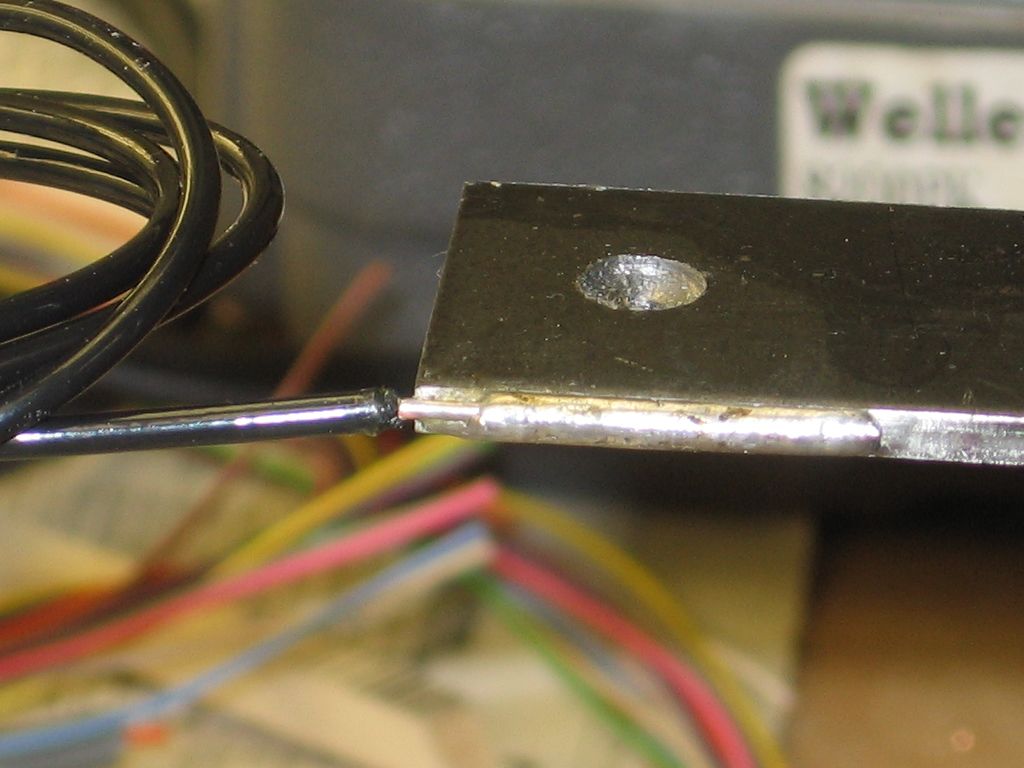
Gunrunnerjohn talked me into soldering wire connections to power my track. This is a 16x17 layout with Gargraves track and Ross turnouts, divided into 8 electrical blocks. Operation is DCS and TMCC through DCS using 3 TIUs with all outputs fixed, in SUPER mode. No conventional operation and no Legacy.

I hadn't wanted to solder the track and was looking for some way to attach wires from the TIUs to the track without soldering. GRJ suggested that everything would be more reliable if I just soldered the connections. I believe he is right and off I went with Weller's big-butt 240 watt soldering gun.

It has all worked out pretty well EXCEPT that some sections of Gargraves track will not take solder no matter what I do. Oddly, this only occurs on the shiny outer rails. The black center rail ALWAYS takes solder (so far). I grind a clean area along the base of the rail, tin the wire and then tin the clean area of the rail. Then I apply heat and solder and 85% of the time, this all goes smoothly and I march on.

15% of the time, the shiny outer rails on a "problem track section" will not take solder. I tried different fluxes, I tried 60/40 solder and 63/37 solder (no lead-free--all real solder), I tried more aggressively grinding the base of the rail and .... no good. Finally, for these relatively few track sections, I dug out a tiny drill bit, drilled a hole in the base of the rail, wrapped a wire around a #2-32 sheet metal screw and screwed a wire connection to the rail. This yields good continuity but certainly not the reliability of a soldered connection.

Has anyone else seen this and found a solution?

Don Merz

Original Post

Replies sorted oldest to newest

Gunrunnerjohn talked me into soldering wire connections to power my track. This is a 16x17 layout with Gargraves track and Ross turnouts, divided into 8 electrical blocks. Operation is DCS and TMCC through DCS using 3 TIUs with all outputs fixed, in SUPER mode. No conventional operation and no Legacy.

I hadn't wanted to solder the track and was looking for some way to attach wires from the TIUs to the track without soldering. GRJ suggested that everything would be more reliable if I just soldered the connections. I believe he is right and off I went with Weller's big-butt 240 watt soldering gun.

It has all worked out pretty well EXCEPT that some sections of Gargraves track will not take solder no matter what I do. Oddly, this only occurs on the shiny outer rails. The black center rail ALWAYS takes solder (so far). I grind a clean area along the base of the rail, tin the wire and then tin the clean area of the rail. Then I apply heat and solder and 85% of the time, this all goes smoothly and I march on.

15% of the time, the shiny outer rails on a "problem track section" will not take solder. I tried different fluxes, I tried 60/40 solder and 63/37 solder (no lead-free--all real solder), I tried more aggressively grinding the base of the rail and .... no good. Finally, for these relatively few track sections, I dug out a tiny drill bit, drilled a hole in the base of the rail, wrapped a wire around a #2-32 sheet metal screw and screwed a wire connection to the rail. This yields good continuity but certainly not the reliability of a soldered connection.

Has anyone else seen this and found a solution?

Don Merz

Hmm, the fact that it is only some sections is weird, that would imply either the metal in that section had a significantly different composition then the other sections where it worked or there is something on the surface of it stopping a good solder joint. If you ground it down, though, that would kind of rule out some kind of surface contaminant.

I assume you are soldering them with them on the layout and fully in place. If possible, just as an experiment, I would take one of the problem sections off the layout (obviously, again, if at all possible) and try soldering it by itself. I wonder if maybe being where it is in the layout, the heat is being dissipated because it is connected in (the sections electrically connected are also thermally connected) and it is just too big a heat sink, so you aren't getting a hot enough joint. By taking it off by itself might test out that theory...the other place if the track can come up is to try soldering on the bottom of the rail, I used to do that with tubular track back in the day.

I suspect you have Stainless mixed as noted above.  I had zero issues soldering to my Gargraves or Ross tin plated track.  For the blackened rails, I used a Cratex wheel to knock off the plating to solder to those.  For the tin outside rails I didn't do anything but apply heat with my Weller 100/140 gun and feed solder into the tip.  For old track, you might need to scuff it a bit to solder it, all of my track was new out of the box as well as the switches.

Artie--I am doing my best not to remove the track. Since this problem only affects a small percentage of my wiring, I am going to trust the screw attachment. If I have to lift the track section, I might as well replace it with a known-good track section.

GRJ and friends--it is quite possible that some stainless rail is mixed in here. I bought almost all my track USED, like everything else on this railroad! So Lord knows what is in there. I guess I am lucky that the problem is not more widespread.

Fastman--that magnet idea is worth trying and I will do that ASAP.

Don

Note: most tubular track is steel, with a very thin galvanized coating.   The solder will adhere well to the galvanize.  If you remove the galvanize, the project becomes much harder.  A careful clean, plumber' soldering flux might help.  I was able to solder copper wire to this steel, part of a turntable.

Also these brass washers to the turntable shaft.  Map gas /propane torch was used.
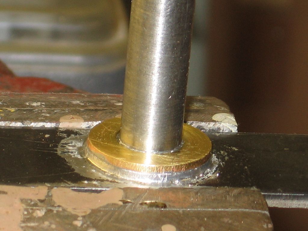
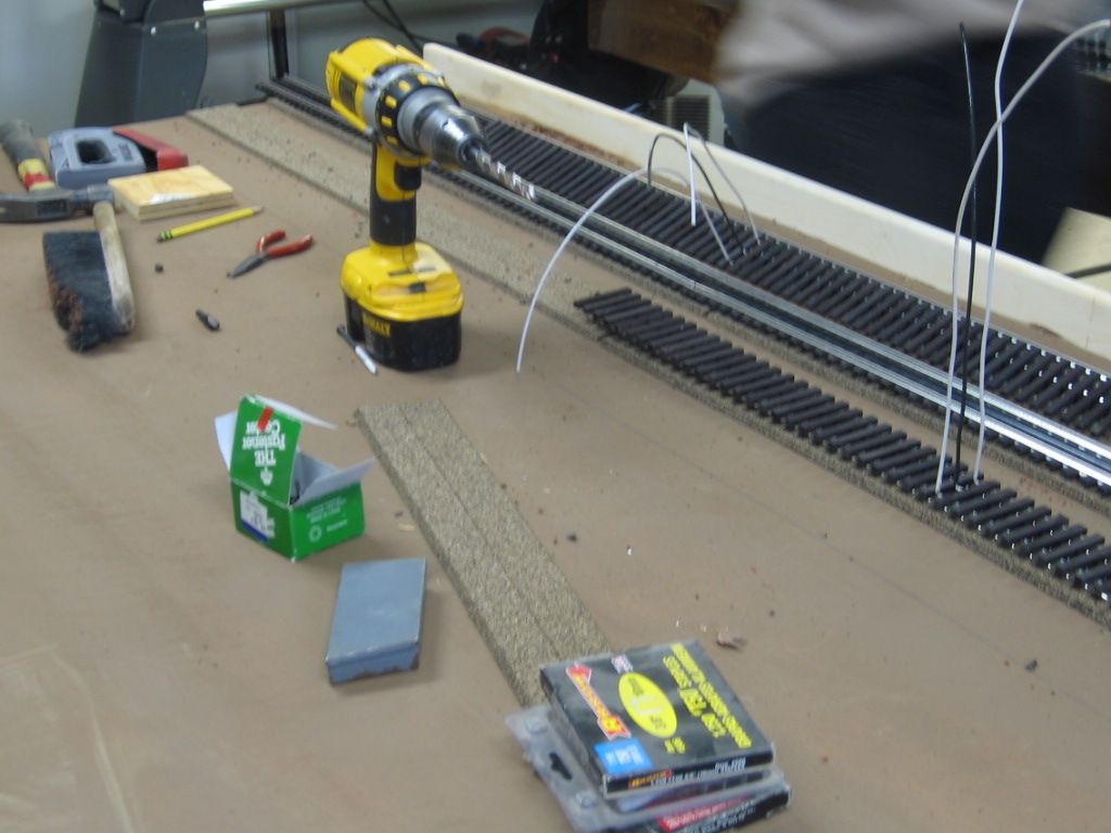
Solder to the bottom of Gargraves, with Solid14 ga. wire leads. A couple of very old Weller Soldering guns.

Last edited by Mike CT

Bigkid--I like your reasoning. But the 240 watt gun I am using should heat anything. Heck, if you hold down the button too long, the copper gun tip starts to droop!

Don

That reasoning was proof of Occam's Razor, that you come up with a convoluted solution and forget the obvious (that Gargraves made stainless steel). I also thought "maybe the iron isn't hot enough" but then I re-read the message and realized what you were using, I had one of those beasts, these days I probably would have trouble picking it up *lol*

Hard to believe a soldering gun isn't getting hot enough to solder to Gargraves Tinplate track!  I soldered hundreds of connections to my track during my build, and I did it with a 30 year old Weller 100/140 soldering gun.  Obviously, I made sure the tip was good and the tip nuts were tight.  With those obvious common sense steps, the gun got plenty hot to quickly solder to the Gargraves track and the Ross Switches.  Note that you do have to take the blackening off the center rails to solder to those, but I hope that's obvious.

Hard to believe a soldering gun isn't getting hot enough to solder to Gargraves Tinplate track!  I soldered hundreds of connections to my track during my build, and I did it with a 30 year old Weller 100/140 soldering gun.  Obviously, I made sure the tip was good and the tip nuts were tight.  With those obvious common sense steps, the gun got plenty hot to quickly solder to the Gargraves track and the Ross Switches.  Note that you do have to take the blackening off the center rails to solder to those, but I hope that's obvious.

Sometimes the low voltage connects, end of gun to the replace-able soldering tips can become loose, or slightly corroded. Most Weller equipment has replace-able tips.  Some of the guns had two heat intensities built into the trigger, another part that can go bad after 30 years.  I was also able to replace the small light bulbs near the soldering tip.

John and Mike, Yes, I made sure the tip was cleaned and tinned, nuts tightened, the blackening was off the center rail, and the 2-position switch seemed to be working.  I forgot one thing when I was soldering a few weeks ago.  This is the soldering gun that I foolishly jammed into my wrist when it was hot.  My DNA must have damaged the tip over time.    Yah, that's it. 

I thought I had new tips, but who knows after many years, so I bought two new ones.  Hey, it solders to GarGraves rail fine now.  I know I had the mishap over 30 years ago, because our older daughter hadn't been born, and she turn 30 in a month.  Bad DNA. 

I used my soldering pencil when I built HO layouts so I didn't melt the plastic ties, so the Weller hadn't been out of the box for years.

Last edited by Mark Boyce

I have soldered to Gargraves-a task I do not relish even with catsup and mustard

and I have used the Gargraves power connections-the 911-1 Solder-less connectors.

They are a pain to install but electrically I find that they are sufficient to the task, and easier to use than soldering  

And I have found that if you take a spare wooden tie, and set the connector on it, after aligning the tab into the rail slot-and using a small “persuader”...one solid tap drives the tab into the slot, and then sliding the rails closer to the connector makes a useful mechanical connection.

The drill idea has merit.
But I’d rather take a few minutes to get power to the rails than spend a frustrating 5-15 minutes soldering with all it entails.

but

to each their own

@1drummer posted:

I have soldered to Gargraves-a task I do not relish even with catsup and mustard

...  SNIP ...

But I’d rather take a few minutes to get power to the rails than spend a frustrating 5-15 minutes soldering with all it entails.

5-15 minutes???  I really should post a track soldering video!  I can't imagine what you're doing to take five minutes to make a solder connection, never mind 15 minutes!

Note that we're talking about tinplate track here, it's very easy to solder!

Last edited by gunrunnerjohn

Well, let's see....1. Check length of feeder wire(s) needed, 2) Cut feeder wire(s), 3) Strip ends of feeders, 4) Tin feeder ends, 5) Grind rails at solder points to bare metal, 6) Tin rails, 7) Drill hole through roadbed for feeders to run underneath, 8) Route wires down through hole to junction box or other connection point, 9) Solder feeders to rails, 10) Test continuity and for shorts between center rail and outer rails, and finally 11) Correct any sloppy soldering and ensure stock rolls smoothly over connection points...then move on to the next feeder.

5 to 15 minutes? Yep, sounds right.

Don Merz

You guys really need to work on your soldering.  If it took me 15 minutes for each track drop, I'd probably still be wiring my power.

First off Don, let's not stuff the ballot box here, we're talking about making the solder joint.  You have to prep the feeder wires whether you solder or use some other connection point.  You also have to drill through the roadbed, route the wires, check the continuity, etc.  Those are all tasks for any wiring of power drops to the track.

I wasn't the one that started the conversation of how difficult it is to solder to Gargraves track.

I use a gun because I find it more convenient, and the quick and plentiful heat makes the soldering job quick and easy.  I grab the gun and squeeze the trigger, by the time I have it in position to solder, it's up to temperature, no time wasted.

Truthfully, all the other stuff you mentioned doing a track drop takes far more time than the quick solder connection to the track.  If you're using new or newer Gargraves tinplate, the only cleaning you have to do is to remove the blackening from the center rail, I didn't do anything but solder to the outside tin rails for any of the Gargraves track or Ross switches.  I also just use .031 diameter 63/37 Rosin Core solder for the job, I don't screw around with extra flux, etc., it's not needed.

I have to admit, I was an electronics technician dating back to 1976, and I have always felt wiring whether soldering or using some kind of terminals with or without attaching lugs to the wires takes time.  I do have to admit, I have always been sort of a klutz, and with arthritis setting in early, some of those tasks have become harder.  Therefore, that is one layout building task I do not like

Back when I was in my mid 40's a younger fellow in his 20's came to work with us.  He had been required to become NASA soldering certified at his previous job.  Wow, could he could he make a terrific solder connection quickly!  He was all the things in a technician that I was not.  But, I was all the things that he was not.  We complimented each other very well.

That is an excellent point, Jim.  When we strip the insulation off the wire, we 'call it clean', but the rail defiantly isn't.  I bought 3 Ross switches recently.  The two that were identical had a lot of an oily substance on them that I hadn't seen on their switches before.  It made me realize there must be some of whatever that was in the process of making all of them.

Well anyone can post a video if they prefer.
but that won’t change the reality I have encountered getting sufficient heat to the rail, with flux and without, then getting the tinned wire and the rail to join in a satisfactory joint

And I would be willing to compare my Soldering Experience and Expertise against anyone.

I wonder why in any group theres always that one individual who has to use their own experience as a generalization application for everyone. As if there can be no other variables in existence
when in fact there are many.

The point is, using the Gargraves connector is easier and faster and it doesn’t affect the rails  -it’s almost as if it was tailor made for the job😁

Soldering Gargraves track. How about contacting me via e mail,I will give you my mail address, and you can send me a 4 or 5 inch piece of the track that won't solder. The ups store [and others] sell a 6 inch padded manila envelope that will work. I have some experience, and would like to try. Be sure to include return address and phone # if you want. Charlie.

Last edited by fastman
@1drummer posted:
I wonder why in any group theres always that one individual who has to use their own experience as a generalization application for everyone. As if there can be no other variables in existence when in fact there are many.

Since this seems obviously targeted to my posts, exactly what variables are you posting about.  You didn't mention the exact type of track.  Presuming your boasts about your soldering experience are true, it would not be stainless, as we know that would greatly increase the difficulty.  Maybe you're using the wrong iron or solder, again you didn't specify what you use.

Well anyone can post a video if they prefer.
but that won’t change the reality I have encountered getting sufficient heat to the rail, with flux and without, then getting the tinned wire and the rail to join in a satisfactory joint

That's the part I'm trying to understand.  First off, I never needed more flux than the Rosin Core solder provides, that that's a non-issue.  My 100/140W gun gets plenty of heat where I need it to solder to the rail, and I've also used the same gun on countless joints on Atlas solid rail connections for our club modules.

And I would be willing to compare my Soldering Experience and Expertise against anyone.

All evidence to the contrary.

We've been very fortunate in this thread in a number of ways--many knowledgable people have commented and we discovered that quite a number of folks on OGRF have seen this issue. That alone is worth the price of admission. But we were also gifted with a number of strong solutions including ways to make sure our soldering process is following "best practices" and alternatives such as the spade lug connection and my own "drill a hole in the rail and use a number 2 sheet metal screw" to make the connection.

Separately, I also looked into using a conductive glue, but the best products are VERY expensive so I discarded that approach.

Finally I neglected to report to my kind responders that I DID try the magnet on the rails--I tested both the ones that take solder and the ones that won't with the result (wait for it.....) that they are the same. The magnet has the same attraction to both "good" and "bad" rails. Ugh--I thought that test was going to be conclusive. But no, Murphy's Law applies. Classic.

Someone asked for a sample of the "bad" rail. I'll be glad to send this. I have decided to uproot the one "bad" section and replace it because it's in a critiocal spot entering my only big reverse loop. I can send a sample of "bad rail" to anyone who may be interested. My email is in my profile.

So far I have soldered just shy of 100 connections to the layout (a drop in the bucket--don't remind me!) and just TWO of them won't take solder. Bizarre. One of the cartoon strips--was it Mr. Magoo?--used to have a character that walked around while a rain cloud stayed over him pouring down rain wherever he went. That is how this problem makes me feel!

Thanks to all!

Don Merz

Add Reply

Post
×
×
×
×
Link copied to your clipboard.
×
×