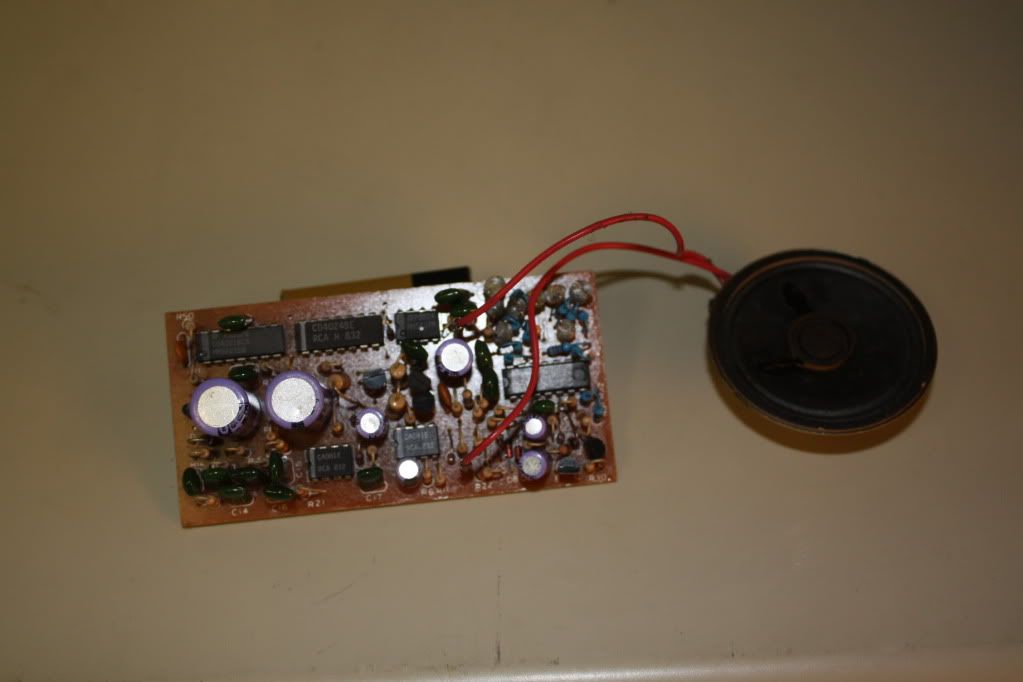
I picked up a Lionel SOS board with whistle, part # 690-8215T-15
Here is a pic of it.
I know where the speaker goes, but there is no info as to where the other wires go can anyone help?

|


|
I picked up a Lionel SOS board with whistle, part # 690-8215T-15
Here is a pic of it.
I know where the speaker goes, but there is no info as to where the other wires go can anyone help?

Replies sorted oldest to newest
SOS boards had one wire that ran forward into the engine to hook to a Cherry switch to "time" the chuff sound; it would also need a power wire + ground wire to power the board.
I am in same boat. 3 pin version. Can not find a part number but looks like later version above with multiple chips.
Anyone suggest a simple hookup.
I assume one is power, one is ground and when is for chuff.
Do not need to synchronize chuff with smoke.
Would like to put in a stand alone generic tender to use with different engines.
What is easiest and what parts are available? Hall sensor and magnet or reed switch?
Here's a photo of one in place. As you can see it's the AC version - I don't know if there's any difference on the one for a can motor or not. The tender on this one doesn't have a power pickup so the power wires go to the locomotive. The three tether wires are: black and blue to the two ends of the field coil on the motor; brown is the chuff. The brown goes to the hot side of the puffer-type smoke unit, which presumably triggers the chuff. I didn't notice which end of the field goes to ground, but you can probably figure it out from the photo. You can zoom in on the photo by clicking on it. The two yellow wires go to an on-off switch that cuts off the chuff. If I remember right, the whistle still works when you turn off the steam sound. I haven't run this thing in years; it's sitting in pieces in a box waiting for a repaint and a TMCC conversion.
Here's the overall view:
And here's a closeup of the connections to the board.
That SOS board was first used in the Southern Mikado of the
FARR series of 1983-84 and the later 783,784,785 Hudsons.
The board has 3 wires for center rail, outside rail, and a wire
connected to the AC motor brush for the pulses to count
and divide for the chuff sound.The chuff rate could be changed
by moving a jumper on the count down circuit. There is a
capacitor connected to the motor that is too small so changing
to a larger cap makes the chuff work much better.
There was a drawing of that board in the June 1993 issue
of The Lion Roars. If you want a copy, send me your
eMail address and I will try to scan it in and eMail it.
After reading pa's post, maybe I misidentified the three colored leads. Maybe the brown, which goes to the hot side of the smoke unit, is center rail, the blue, which goes to one end of the field coil, is outer rail, and the black, which goes to the other end of the field, is chuff. That would make sense, since blue and brown carry power to the motor in most of the 0 gauge locomotives I've worked on.
The board has 3 wires for center rail, outside rail, and a wire
connected to the AC motor brush for the pulses to count
and divide for the chuff sound.
The brown wire connects to 2 diodes and a 240 k resistor,
The black wire connects to the junction of 2 470uf caps.
The blue wire connects to a 330 pf cap. The black or brown wire
can connect to the center rail and the other wire to the outside
rail. The whistle will work without being selective of
which power connection is to the center rail.The blue wire
connects to a motor brush for the pulses for the chuff.
OK, I still had it wrong. Thanks for the correction. Some of those wires disappear into the locomotive chassis and I didn't trace them all the way.
Access to this requires an OGR Forum Supporting Membership
