OK....looks like the OP deleted his subject/title and question/statement so after reading through ALL of the responses/posts, I decided to do the best I could to come up with the subject/title.  Some of the discussion is interesting and has good information/facts so rather than deleting the entire thread....I did this.  If you want to email me with a better more appropriate title/subject, please feel free to do so...

Alan

Last edited by OGR CEO-PUBLISHER
Original Post

Replies sorted oldest to newest

gibson man posted:

This isn't really hobby related...but more directed to any old hands who might be in the know...

Why, on a steam engine, are all drive components located outside the wheels instead of between the wheels? 

For easy access of all the various side rod bearings, plus the valve gear and valves/cylinders. All those rotating components required constant inspection and lubrication, and whenever the train was stopped the Engineer was usually walking around inspecting and "oiling around" his locomotive.

Steam engines could have been designed similar to automobiles, with the axles cranked, all rods and bearings enclosed in a wet sump, cylinders external connected by the piston rods...all center-mounted.

You forget that between the frame members that support all that weight, are the brake rigging and spring rigging with its equalizing levers and rods. There were some 3 cylinder steam locomotives used in the U.S. and throughout Europe, with the center cylinder drive a cranked axle. Those were generally maintenance nightmares! 

Wouldn't this have improved on the constant maintenance requirements? 

Absolutely NOT! Think about how easy and fast it was to replace a few worn-out side rod bearings, when all that machinery was/is on the outside. A simple task of greasing the rod bearings would have had to be done with the engine over a pit between the rails for access.

It sure seems like there was room for improvement, still, that could have kept steam competitive...

Nope. Remember that the best and finest steam locomotives ever designed and built were only 10% efficient at the rail. The diesel electric locomotive quickly eliminated the labor intensive, and inefficient steam locomotive. Also overlooked by many "enthusiasts" was the Water Service Department on every major railroad, which employed thousands of men that were responsible for testing water sources throughout their own railroad, and making sure that each and every water supply was properly treated with chemicals in order to protect the insides of all their steam locomotive boilers. None of those people were need nor required for diesel electric units!

Anyone know?


I’m sure it was just for the reasons you say “ease of maintenance”. All those parts that need to be readily accessed can be and from the ground not ladders or catwalks. On Shays the moving parts were all accessible from one side for ease of maintenance. Also Steam engine Development ended a good bit before the end. The last mainline steam engines built in the 40’s followed designs made in the late 1910s.   

In other countries notably England many steamers did have international moving parts as well as other designs that were like those in the States. 


Another reason why there is no need for an oil-filled sump or crankcase like a car is the RPM range that the steam locomotive operates in.

A typical automobile engine idles at 500-800 RPM and will redline somewhere around 5,000 to 6,000 RPM. The lubrication demands for machinery moving that fast call for relatively thin oil pumped under pressure through bearings running at clearances as tight as .005 inches. 

A steam locomotive “idles” at zero RPM. At 70 mph the rotating machinery is turning at only 300-400 RPM, depending on the driver diameter. The loads on the bearings are higher of course, but the bearing clearances are .015 to .030 inches. Those larger clearances, combined with the relatively slow rotation speed allows for a totally different approach to lubrication. Instead of oil, the rod bearings are lubed with a very heavy grease. This grease is extruded into 1” diameter sticks for use in a huge “grease gun” powered by compressed air. This grease is so heavy that you can handle a stick of it and not get anything on your hands.

When a steam locomotive crew “shoots the rods” with the Alemite gun (the big grease gun) they fill the space between the bearing and the rod with the heavy grease. Because of the slow rotation speed, the grease just stays where it is, providing the lube the rod bearings need. Over a period of time and distance that grease will slowly be depleted as it is squeezed out of the bearing area. This happens over 100 - 150 miles, when the crew will have to stop and shoot the rods again.

Last edited by Rich Melvin

HOT WATER, SILVER LAKE, RUSTY TRAQUE and Rich Melvin have made the case for the mechanical layout of steam locomotives. Not much I can add. However, poppet valves would not have added much to engine efficiency. The biggest increases in thermal efficiency would have come from higher steam temperature and pressure, and a closed system - that is, one in which a condenser returns all the condensed exhaust steam to be reheated and used again. This would have eliminated all the extra water the tender had to carry, but it was never considered to be practical.

MELGAR

Last edited by MELGAR

The poor British mechanics spent a lot of their time crawling underneath locomotives or working in inspection pits because EVERYTHING was inside between the frames on many of the older types - maintenance intensive. As mentioned above the American open style was a lot more maintenance-friendly. 

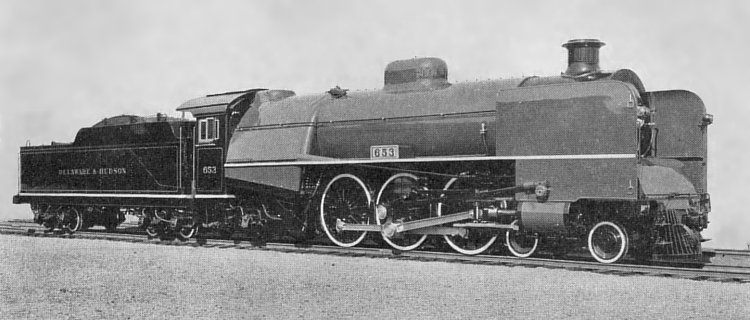
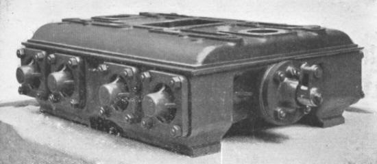
You would have seen the more modern stationary steam engines become more enclosed with sumps, etc. like uniflow engines for example. The Lentz poppet valve system was enclosed and used here and there on both sides of the Atlantic, even on some inside cylinder British designs.

Image result for lentz poppet valve delaware hudson


Mono-bloc valve box for No 8280

https://www.lner.info/article/.../valvegear/lentz.php

gibson man posted:

My only reason for suggesting that is that constant lube provided by a wet sump would likely negate required maintenance until significantly longer periods...maintenance cost reductions...

Very sorry but, you are incorrect.

If the drive train were isolated in a sump...at required intervals you would shop the engine...hoist the boiler off the package...and work or rebuild same as an automotive engine.

You really have no idea about real steam locomotives, do you?

Overhead poppet valves...cam driven, cam located in the sump...etc...

Nope.

Was just curious...


gibson man posted:

Nope...not an expert. 

All I was suggesting, in a roundabout way, is that the same technology that allows an automobile to travel a fairly significant distance, and need only minor maintenance until a large number of miles traveled, could have been applied to steam applications. 

No it couldn't, because steam locomotive design and development go back to the 1850s in the U.S., and further back into the early 1800s in Great Britton. The automotive drive line technology you are referring to didn't come along, as reliable transportation, until about the middle of the 1916 era. By that time, steam locomotives had gotten huge and as the "Super Power" era of steam locomotives began in about 1927, there was still none of the technology you refer to, in the automotive industry. Also, don't forget about the amount of work that a steam locomotive was expected to do, day in and day out.

It would require a departure in thinking from established practice...if possible at all.

No big deal...just asking questions. 


gibson man posted:

All I was suggesting, in a roundabout way, is that the same technology that allows an automobile to travel a fairly significant distance, and need only minor maintenance until a large number of miles traveled, could have been applied to steam applications. 


How, exactly? How would it even be possible, to have side and main rods flailing about in some oil-filled sump? How much oil would end up on the ground?

Like Rich said, you use GREASE in rod bearings, not oil.

Like many people here, I have seen N&W J close up (I even got to go into her firebox). I was surprised to see that I could not see daylight on the other side when I looked through her frames from one side to the other. That place is PACKED with equipment.

Working between the frames of a steam engine is no fun. I can tell you that from experience as well.

You might need to think this ne through a little bit more.

smd4 posted:
gibson man posted:

All I was suggesting, in a roundabout way, is that the same technology that allows an automobile to travel a fairly significant distance, and need only minor maintenance until a large number of miles traveled, could have been applied to steam applications. 


How, exactly? How would it even be possible, to have side and main rods flailing about in some oil-filled sump? How much oil would end up on the ground?

Also, that sump would have to have the driver axles pass through it, all of which are independently sprung, opening up more opportunities for leakage.  I don't think you could even seal that off effectively.

The automotive crankshaft is fixed in position and does not move up and down with the irregularities of the road or the vibration of the motor and transmission.

Rusty

Last edited by Rusty Traque
Rusty Traque posted:
smd4 posted:
gibson man posted:

All I was suggesting, in a roundabout way, is that the same technology that allows an automobile to travel a fairly significant distance, and need only minor maintenance until a large number of miles traveled, could have been applied to steam applications. 


How, exactly? How would it even be possible, to have side and main rods flailing about in some oil-filled sump? How much oil would end up on the ground?

Also, that sump would have to have the driver axles pass through it, opening up more opportunities for leakage.

Rusty

Exactly. And think about all that added weight in oil and steel. And can you imagine how much fun it would be when you have to adjust shoes and wedges, or, heaven forbid, need to replace a wheelset?

Last edited by smd4

Here's a British newsreel-type video that shows a minor maintenance procedure, and even with the very narrow job-description niches, it shows the ton of work that even a modernized design needed. The design is British Railways "Standard" which adopted the American all-outside motion - finally. Picture the work that the 1900s designs needed, and many of them were still around in the 1950s. You can see how dieselization brought job cuts numbering many thousands.

Last edited by Firewood

I think the closest analogue to what you were suggesting, Gibson Man, would be the adaptation of roller bearings to the main rotating parts in the running gear.  Roller bearings were sealed with self-contained lubrication and did not require frequent attention as plain bearings did.  Roller bearings were widely applied to the axles of most modern steam steam locomotives, and less often to the rods and valve linkage.  Locomotives like the New York Central Niagara and Norfolk & Western J class 4-8-4’s were notable examples with roller bearings applied extensively throughout the running gear including all axles and side and main rods.  This was a key reason why they each were able to rack up so many miles per month.  On the high speed New York Central, Niagaras could accumulate over 20,000 miles per month, a figure that rivaled the diesels of the era.

Scott Griggs

Louisville, KY

I think the problem is you are visualizing an internal combustion engine (whether diesel or gas) and assuming that their efficiency has to do with their layout and the fact that they use sump lubrication versus what you see on steam engines. External steam engines are less efficient than internal combustion engines but that is thermodynamics, has to do with the base and high end temp differential, the most efficient steam engine could not approach the efficiency of a typical internal combustion engine. I can understand the idea of 'self lubricating' bearings and the like, but as Rich pointed out on a steam engine they don't go at the speeds of an internal combustion engine, so the lubrication can be simpler.  

Finally found what I was looking for.  This is a driver set from a 3 cylinder locomotive:

3 cyl driver

It illustrates the problem with having an oil sump between the frames to lubricate rods.  The sump would have to be almost as tall as the drivers in order to be covered, otherwise all that precious oil would easily get contaminated and/or ejected out as the locomotive moved at speed.  Also, as mentioned before, the axles would have to pass through the sides of the sump and it would be impossible to drop one set of drivers for turning or replacement.

We'd probably be looking at least 100-200 gallons of oil to keep the bottom of the stroke in oil.  Slightly more than the 4-5 quarts of oil a car engine needs in its nice tight closed system.

There would be little clearance of the sump over the railheads (switches, crossings both rail and road) and prone to damage from below.  Plus, how would one seal off the front where the main rods pass through to meet the crossheads?

Rusty

Attachments

Images (1)
  • 3 cyl driver
Rusty Traque posted:

The sump would have to be almost as tall as the drivers in order to be covered, otherwise all that precious oil would easily get contaminated and/or ejected out as the locomotive moved at speed.  Also, as mentioned before, the axles would have to pass through the sides of the sump and it would be impossible to drop one set of drivers for turning or replacement.

We'd probably be looking at least 100-200 gallons of oil to keep the bottom of the stroke in oil.  Slightly more than the 4-5 quarts of oil a car engine needs in its nice tight closed system.

There would be little clearance of the sump over the railheads (switches, crossings both rail and road) and prone to damage from below.  Plus, how would one seal off the front where the main rods pass through to meet the crossheads?

Rusty

All good points, and illustrative of why the premise of this thread wasn't well-thought-out.

Automobiles = internal combustion, Steam engines = external combustion. They're different and each have their own strengths and limitations, you can't readily apply what works for one to the other. I suspect the issue of wanting more things to be internal on engines was solved with the development of diesel-electric locomotives.

gibson man posted:

As far as the mechanism...again just bench-racing, and knowing steam is way too inefficient...try this:

Two cylinders...horizontally opposed...centerline crankshaft...enclosed in a separate housing mounted to frame such that it can be unbolted slid out the front of the engine as an assembly...

Driveshaft runs length required to interface all drive axles...

With the exception of direct drive to all axles, that's called a Heisler:

Heisler Pacific Lumber 9

Driving all axles you'd have a Dunkirk:

Dunkirk Blasidall 2

Climaxes, Shays and Willamette's (similar to a Shay)  drove all axles, but lacked the V2.

Climax 564

Shay J Neils 5

 Rusty


Attachments

Images (4)
  • Heisler Pacific Lumber 9
  • Dunkirk Blasidall 2
  • Climax 564
  • Shay J Neils 5
Last edited by Rusty Traque
gibson man posted:

Ok...so the killer really is the inefficiency of the steam process...not the mechanism.

Can't be overcome. 

As far as the mechanism...again just bench-racing, and knowing steam is way too inefficient...try this:

Two cylinders...horizontally opposed...centerline crankshaft...enclosed in a separate housing mounted to frame such that it can be unbolted slid out the front of the engine as an assembly...

Driveshaft runs length required to interface all drive axles...

Drive axles resemble modified versions of huge dump truck drive axles, with pinions rotated similar to army trucks...pointing upward...driveshaft interfacing with each axle and passing through to next axle to transmit power...axle housing suspended as required to allow movement as needed...

Everything direct drive...gear ratios selectable...

Unknowns (for me)...the biggest (to me) would be the overall width of two opposed cylinders with, say, a twenty six inch stroke...ground clearance not necessarily a problem...

Hey I'm just bench racing for fun...but let the rock throwing resume...lol...

I don't know why people are throwing rocks, it is one of the irritating things on  here and in the 'real train' and model train community, where those who think they know a great deal seem to get something out of putting down those who ask 'silly' questions (and then wonder why the outside world, who have dealt with the less than charitable "rail enthusiast' or 'model train enthusiast', tend to have negative impressions about the communities), I don't know if they think it is a way of showing how much better they are, or it is their natural personality, but I wish they wouldn't do it...

And yes, the real issue is the inherent inefficiency of steam external combusion (a steam turbine can be orders of magnitude more efficient, but that is a different beast).  Your concept if I understand it wouldn't buy you anything, you now have introduced all kinds of complexities, the connection between the cylinders and the crankshaft,then the gears required to translate the motion of the shaft to drive the wheels. Besides the complexity this introduces (and increasing the risk of breakdowns),you are adding a lot of friction into the equation as well with all those power redirects and gearing.

If you look at the external steam locotomotive, you have a shaft coming out of the piston that attaches to the drive wheels, while there are pivots involved it is a lot less moving parts then what you proposed above.  I suspect internal components for a steam engine would be more about having some sort of 'clean' appearance or maybe some idea of safety (?...like when standing still the drive gear isn't particularly a problem, and steam engines accelerate so slowly that it is unlikely someone is going to get whacked by a drive rod or some other external gear...maybe scalded by steam from the piston being released.....)

And again, as others pointed out, having it 'all hang out' makes it a lot easier to maintain. Compare that for example brilliant car engine layout/design where you have to take half the engine apart to replace spark plugs or remove half the exhaust system to get at the oil filter, and you get the idea. Having this complicated stuff under the engine would make getting at it difficult, on a typical steam locomotive you can walk up to it and perform maintainance for a lot of basic things. 

bigkid posted:

I don't know why people are throwing rocks, it is one of the irritating things on  here and in the 'real train' and model train community, where those who think they know a great deal seem to get something out of putting down those who ask 'silly' questions (and then wonder why the outside world, who have dealt with the less than charitable "rail enthusiast' or 'model train enthusiast', tend to have negative impressions about the communities), I don't know if they think it is a way of showing how much better they are, or it is their natural personality, but I wish they wouldn't do it...

You're right--it's all about attitude.

Railroaders are some of the nicest, most patient people I know. They love taking the time to explain the intricacies of things like steam locomotives to people with honest, inquiring minds.

But when someone with little to no experience comes out making statements to support their question ("Steam engines could have been designed similar to automobiles, with the axles cranked, all rods and bearings enclosed in a wet sump, cylinders external connected by the piston rods...all center-mounted.... sure seems like there was room for improvement, still, that could have kept steam competitive"), then we have a bit of a problem.


Last edited by smd4

How to initiate an stone-throwing epic...from very little knowledge

Yep, I can't think of anyone who could have done it better, you must be an expert at it...

When you consider that many of the best thinkers in mechanical engineering were devoted to steam locomotive design for over 100 years, and that gaining efficiency was a high priority for all of that time, doesn't it follow that if what you propose was the way to go, then they would have already done it, say 120 years ago?

It's not like they weren't aware of the concept.  Stoker engines, mounted under the cabs of a majority of large steam locomotives, use exactly the concept that you advocate.  Since they never followed through with the main machinery, there must have been a reason -- it wasn't practical.


Last edited by Kelly Anderson

Gibson, you've gotten feedback and lengthy explanations from some of the most knowledgeable people in steam. You really should be thanking Jack, Rich, Kelly and Rusty for taking the time to respond to your query, instead of taking your ball and going home.

Like I said...it's all about attitude.

gibson man posted:

Well...I'm embarrassed by my lack of understanding...I've offended people I respect...and if I was intelligent enough to delete the thread I would. 

My takeaway really is to keep my idle speculation to myself rather than say 'yeh...but what if...'...

I apologize to everyone for even posing the question. 

Just my opinion; maybe in the future just ask questions, instead of making closed end statements, about a subject you are unfamiliar with.

Norm Charbonneau posted:

What about this?

And experimental (chain/piston instead of rods - gets good/weird about 55sec. in):

All that just for the valve gear on a Bullied 4-6-2.  Still has conventional main and side rods.  Plus, British Rail began rebuilding the class, along with replacing the chain valve drive with Walschaerts valve gear which reduced maintenance costs by 60%.  Not all locomotives were converted, however

4-6-2 SR Bullied 34051

Bullied Pacifics, after and before:

4-6-2 Bullied Bullied

As far as the Leader locomotive goes, it obviously didn't get very far.  What a maintenance nightmare.

Rusty

Attachments

Images (2)
  • 4-6-2 SR Bullied 34051
  • 4-6-2 Bullied Bullied
Post
×
×
×
×
Link copied to your clipboard.
×
×