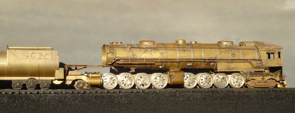
I've started this project a little sooner than I expected. Ping man suggested I begin a project thread so here goes. I chose the Williams for its good value and scale dimensions. When I'm done I hope it will rival the very expensive Korean models. I hope ya'll enjoy the project as I go along.


First I put NWSL 33 inch scale wheels on the engine truck.

Next I unsoldered the pilot and modified it and reshaped it to fit some prototype photos I have. On the first attempt the plow was not flush with pilot beam at the ends and the mount angle was too much.

I re-bent it , re-soldered and painted it. The height is good.

I provided the horn with a hole as the prototype and then detailed the front screen.


Tomorrow will start on the under cab air tanks piping and correct frame profile.

cab forward 1

cab fw 2

cab fw plow 4

cab fw plow 5

engine truck 1

engine truck 2

Attachments

Images (6)
  • cab forward 1
  • cab fw 2
  • cab fw plow 4
  • cab fw plow 5
  • engine truck 1
  • engine truck 2
Last edited by Ron H
Original Post

Replies sorted oldest to newest

I think I got a couple hundred bucks for it.  The drivers were EM-1.  A lot of work remained, and I was unwilling to do it.  


Now that I look at it, the forward frame extension is not perfect.  It should have a radius for the front wheel, but not the back one, and that angle down to the pilot should go further down.  I will see if I have a better photo.  You could fix the Williams frame with a simple piece of thin plastic, glued to the existing frame, just to see how it looks.


If you ever do spring for a KTM, the USH version is the one to get.  The Max Gray version had some serious visual flaws.

Here the frame is painted and installed with the beginning of tank plumbing. With all the additional steam, oil and control lines and rods I'll add under here it will look much better than stock. The loco is not on level track so it appears a little higher than it is.


Also I use both a then rod type solder pistol and a torch depending on what I'm doing. I wish I had a resistance solder unit.

finished frame 1

finished frame 2

finished frame 1

finished frame 2

Attachments

Images (2)
  • finished frame 1
  • finished frame 2

Resistance soldering.

When soldering small brass parts, resistance soldering is nice to keep the heat localized to one small spot.  It's not fun soldering a part only to have another previous part fall off or move because the solder melted.

Mine is as old as dirt (like me).  The foot on/off peddle makes 'life' easier.


They range around 2 C notes.

I remember an article (can't remember where but I think it was model railroader magazine) where they showed you how to make one real cheap.  You can buy the carbon electrodes separate for the project.  You can probably 'google' resistance soldering and find a 'how to'.


Micro mark:

http://www.micromark.com/Searc...z4icQCFdgPgQodaJUAKA     


.

.

.

I just googled resistance soldering and found some youtube and pdf's.  Didn't check them out but that should get you started:

https://www.google.com/search?...e=utf-8&oe=utf-8


resistance soldering

Attachments

Images (1)
  • resistance soldering
Last edited by samparfitt


Soldering alternatives:

One thing I forgot as a replacement for soldering is CA or JB weld.

Granted, these alternatives won't be as strong as solder but on a lot of places (no stress), it's quick and quite durable, ie pipe connectors would be good for CA.  I find it best applying CA by putting some on some wax paper and then using a tooth pick to apply small amounts to the desired surface area.  Using it straight from the bottle usually results in too much being applied (resulting in fingers being also attached to the part!) .  A hardener that comes in a spray can will cure the CA very quickly.  Like solder, the parts can be together and then apply the CA and it will wick into the joint.  The joint needs to be a good fit, else you can use medium or thick CA to fill in the gap.


The JB weld is metal base and I've seen a fin on a RC gas engine glued back on and it didn't fall off from all the vibration.  They have two versions: regular which takes a long time to cure (8 hours) or the quick version that sets up in minutes.  Both have the same tensile strength, the regular just has a high 600 degree temperature strength (which isn't needed on trains).


I'm partial to ZAP CA products.


CAJBWELD

Attachments

Images (1)
  • CAJBWELD
Last edited by samparfitt

I use a very thin 3M medical tape. Put about 8 inches down on cutting board. Cut with an xacto scale 3 to 4 inch strips and wrap. I then coat it with super glue and paint when the glue drys. It takes several hours when finished and it shrinks tighter around the pipe.


Pictured here, are the tape, the lagging on my custom built 1/20.3 K28 and my hand painted engineer. The detail on 1/20.3 scale is easy to fabricate, I'm slowly trying to get where I can do this in 1/48, but I need to buy more tooling.


Ron

tape 2

tape 3

tape 1

Attachments

Images (3)
  • tape 2
  • tape 3
  • tape 1

Doug,


I guess I do. Retired.


Steam guy, more pics of the K28 coming up. I built about 60%. Started with a blank boiler no steps no plumbing etc.,cab and wheels from accucraft. Had to fabricate everything else including the tender and tender trucks. Took about 6 months as I had not retired yet. It is radio controlled.

Last edited by Ron H

Add Reply

Post
×
×
×
×
Link copied to your clipboard.
×
×