
Can you use telephone or cat 5 cable to wire up atlas switches?
Original Post
|
|
Replies sorted oldest to newest
You bet, the typical #22 Telephone Station Cable will work fine. CAT-5 should work as well, though it's typically #24. Note that for very long runs you may need a bit more "kick" to switch, but for 14-20 feet, it should work just fine.
I give you poor folks from Staten Island all the help I can, I think you've had your hands full up there. ![]()
Nice thing is if you have 4 conductor telephone cable you can use red, green and black to denote turnout reverse, normal paths and ground respectively. Yellow is spare or for another purpose.
Yellow is for your bi-polar LED at the switch to indicate position! ![]()
I've been using Phone cable on my Atlas switches since the begining, no problems.
Dan
I've been using it for years, but parallel wire it, meaning I combine 2 wires to make one by twisting the stripped edges at the beginning and ending of the run. I don't want to take any chances of under wiring things.
I use K-Line low-profile O27 switches. They run constant power back to the controller, so to me, it's not just a momentary bit of activity on the wire.
- walt
I don't see any reason to wire these in parallel, that's overkill for switches unless we're talking 50 foot runs to 022 tubular track switches.
Maybe so John, but ever since I read an article recommending to do it I've done it. I still go back to 'better safe than sorry'. Also, since my wires are, for all intents and purposes, "buried" under my Homasote I just mentally feel better doubling up.
Especially since I have a ton of it.
- walt
Since switches use such little power and it just a momentary shot this cable is fine. You can buy me breakfast at Mikes![]()
Since switches use such little power and it just a momentary shot this cable is fine. You can buy me breakfast at Mikes![]()
I was going to buy you lunch on Saturday, but you ditched us and aren't coming. ![]()
![]()
Hi John
Sorry Had too much going on this weekend Next time
RE: the comment "and it just a momentary shot this cable is fine".
I'll revisit my earlier comment: the switch and its controller are in constant "contact" with each other. Since the controllers have lights indicating direction, well at least mine do, to me it's not just a momentary shot.
I would say that the momentary comment is true if you are using non-lighted controllers or something like MTH's AIU.
- walt
The lights are hardly a challenge for any wire that conducts electricity, and certainly not an issue for telephone wire. ![]()
Please include a circuit breaker or fuse in the accessory supply feed that will protect the wire in case there is a short at the far end of the wire. If you have the full power of something like a Lionel brick available, you could have 10 amps in the 22 or 24 gauge wire, and that is probably enough to melt the wire's insulation.
Good point dale, it will certainly melt insulation, I just tried it with the #22 wire and a PW-ZW just to be sure. ![]()
My opinion is all feeds should have circuit protection that matches the size of the wire used.
It's possible that Atlas switches will work better, but I had issues with RealTrax switches on Phone cable. Anything over 10 feet failed to switch properly. I had to double up some wires.
That said, Test your distance, lay out that much wire and wire it to a switch, make sure it works, THEN put it under the layout.
Edit add power supply notes below. 5/17/13 A.M.
I did my switch control work with 18 gauge solid thermostat cable. Available in 2 conductor to at least 10 conductor. Price for thermastat cable, Grainger Supply, is more than phone cable. It worked well for the Atlas 6924 relay board upgrade, there is very limited line loss even for some leads that exceed 40 ft. (8) conductor works well between the switch location and the relay board. (2) additional conductors are needed to power the relay board.
1. Common
2. Through
3. Out
4. Auto non-derail Through
5. Auto non-derail Out
6. Power Routing Through
7. Power Routing Out.
8. Power Routing circuit feed from the switch back to the 6924 relay board. (Fused).
9. (Optional) I did dwarf lights at each switch using the PC boards supplied with Atlas 6931 Dwarf lights. Dwarf lights powered from the 6924 boards would require (3) additional wires.
10. (Optional) Switch pairs used as a cross over, with one control board, involved (2) track circuits. (3) additional wires to duplicate: (6.) Power Routing Through, (7.) Power Routing Out, and (8.) The Second Track circuit back to the 6924 Relay board. (3) Additional wires.
11. Relay board power (2) conductor.
Maximum number of conductors. All options (16). Cat 5 Data/phone cable can be purchases as an (8) conductor/ (4 twisted pair cable) either 22 gauge or 24 gauge.
Relay boards installed.
Note the track power fusing at 3 amps Relay boards 17 and 18 involve two track circuits each, two fuses. One above the board and one marked to the right. The switch motor circuits are a seperate 3 amp fuse. Another 3 amp fused circuit supplies power to the 6924 relay boards.
Accessory Power supply is 18 volts from two PH 135's via fuse blocks. Lower left in picture. Accessory Power is tapped off one of the input leads to the right hand TPC
400. Silver box lower Right.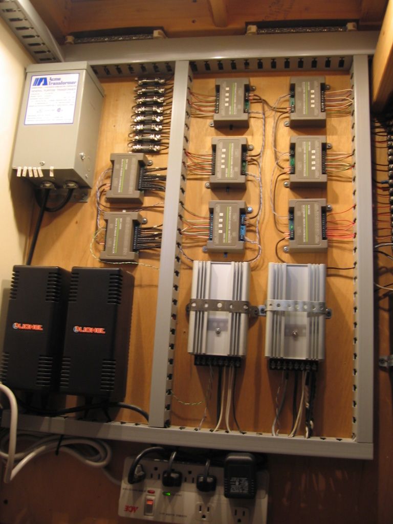
18 Volt accessory fuses are from the blue sta-kon down. Fuses above the blue sta-kon are 12 volt accessory from the transformer upper left of first picture. Most accessory fuses are no more than 3 amps. Center right of grey wire tray in the picture below. Fuse block assemblies pictured. Fuses are standard glass Automotive fuses (AGC) purchased at a local Auto parts store, usually a package of (5).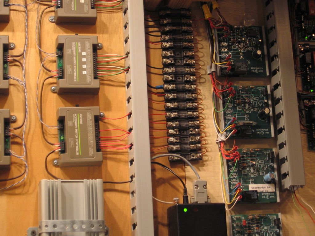
There are small pieces of Cat 5 twisted data wire used in the pictures above to daisy chain TMCC signal between all the TMCC controlled devices pictured. Blue/Blue white and Green/Green white twisted pairs. The only telephone wire I used on my layout.
Fuse block from the Grainger website link is listed above.
I had issues with RealTrax switches on Phone cable. Anything over 10 feet failed to switch properly.
Nobody has mentioned their switch power supply type or the switch voltage. This is important when you might have some line drop. I know my power supply sags a bit when I fire an 022 switch motor. I am using various wires, including CAT5 and some flat ribbon cable. (I split the accessory loads through 5 amp breakers.)
As an experiment, I ran 100 feet of CAT5 cable (24ga, using a single conductor, not doubling up) to a Fastrack switch, the switch is running off 18V track power, not aux power. The switch snaps properly in both directions when commanded from the controller. I tried another one and got the same result.
As an experiment, I ran 100 feet of CAT5 cable (24ga, using a single conductor, not doubling up) to a Fastrack switch, ....................................
OOooooooh! I can only dream and hope for a layout large enough that I need a 100' run from my controller to my switches! That would be nice.
I am sure you just used that much wire John, you probably wish for a larger layout also. Thanks for the experiment and the post. Should ease some fears about the small wire and distance.
Greg
I used a coil of wire, I only wish I needed 100 feet of wire to connect switches! ![]() I figured I'd see if it ran into a problem. I should probably try that with an 022 switch, I suspect that one might benefit from a bit more "beef" in the wire.
I figured I'd see if it ran into a problem. I should probably try that with an 022 switch, I suspect that one might benefit from a bit more "beef" in the wire.
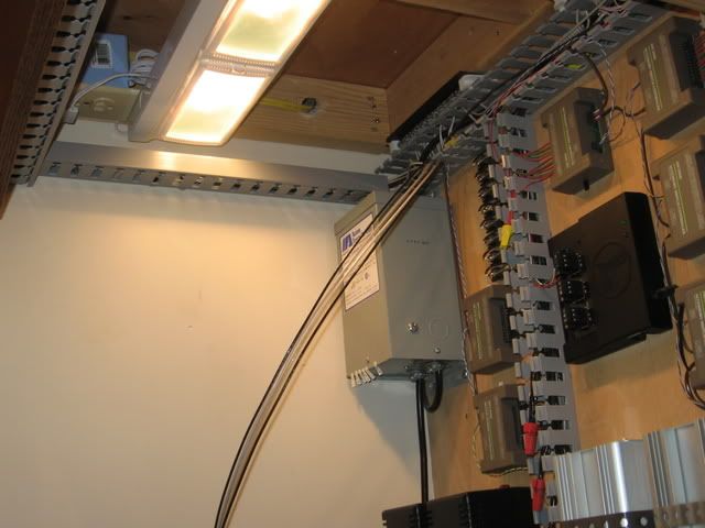
I did a wire pull before setting most of the Atlas 6924 relays. Relay location, up wall, across the ceiling, down wall to the switch location. (45ft). With the trouble involved in the install, the apparent overkill with 18 ga t-stat wire was easily acceptable, IMO. I wasn't doing it twice. A larger layout 100 ft wire pulls would not be uncommon.
Wire pull 6924 relay board location.
Remote layout area.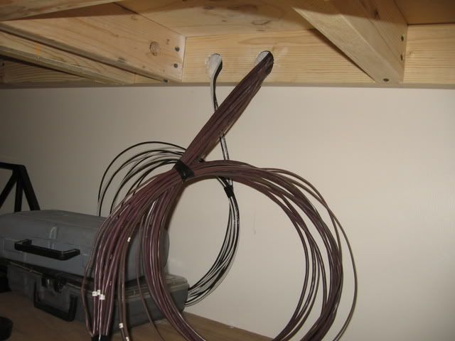
Track circuits at TPC/BPC location. 14 ga solid single strand. White and Black.
As a follow up to Dale's very good point, I am running on 14VAC accessory power for all my switches. I run DCS and did not want to burn out the lights in the switches or melt anything from always being at 18VAC.
Thinking about it, I could have picked off Track power for those farther switches, it would have helped.
Access to this requires an OGR Forum Supporting Membership

