Sorry to get into this again, but I am still fighting with an SC-2 which stops working after an hour or so of powered up time.

I have a new one arriving tomorrow.  I plan to do some internal testing with freeze spray to try to find failing component before swapping in new unit.  One of my questions is where the SC-2 gets power to operate its relays.  In a 6  switch setup, there is no wall wart power and I understand that using the power in terminals in this configuration is not workable.  Since the only wires connected to the SC-2 are the same three which would be connected to the lighted switch controllers which came with the switches, and those three are center common and the thru and out connections, where does the SC-2 get the power to run its relays and internal electronics?

Original Post

Replies sorted oldest to newest

Originally Posted by Ffffreddd:
I believe from the first switch.
Unless they are Fastrack. Then I believe that a mod needs to be made to cut the trace.

Then I think you need a wall wart.
But not an expert on these.

I think it's best to cut the trace and use all six relays. I use a separate transformer (not the wall wart), and connect the COM terminal of the SC-2 to the Legacy base output (which also goes to the outside rails).

The first thing I do to any of my SC2's is to cut the ground trace that connects to output #1.  Then all six relays are totally isolated and you can use any of them for any documented purpose.  You can still power the SC2 from track voltage if you desire, just connect the aux connections to the track.


It's actually pretty difficult to fry the SC2, it has 15 amp relays!


Last edited by gunrunnerjohn

As John mentioned separating common track input on relay #1 seem to simplify things, at least for me.   I use the wall wart for power.  Each relay contact points set is then separate from the internal power common of the SC-2 (All (6) sets).  Note where the trace has been removed/interrupted between the first relay set of contacts, and the two terminal set, used, I believe, for accessory power input.  If it's working intermittent, in may be more of an issue of placement of the SC-2 related to TMCC signal.  It has to be relatively close to a TMCC signal source, i.e. track signal available to the units/locomotives. There is no direct TMCC signal connection to an SC-2 as there is for other TMCC switching devices. (Example TPC or ASC).  Some time ago, excepted procedure was to just not use the (1.) set of contacts, which still allowed for (5) set of independent contacts, more than most, IMO.    Lionel SC-2 reference manual.  Click on the underlined phrase to access.


Last edited by Mike CT
Originally Posted by taylorra:

  Sorry to get into this again, but I am still fighting with an SC-2 which stops working after an hour or so of powered up time.

I have a new one arriving tomorrow.  I plan to do some internal testing with freeze spray to try to find failing component before swapping in new unit.  One of my questions is where the SC-2 gets power to operate its relays.  In a 6  switch setup, there is no wall wart power and I understand that using the power in terminals in this configuration is not workable.  Since the only wires connected to the SC-2 are the same three which would be connected to the lighted switch controllers which came with the switches, and those three are center common and the thru and out connections, where does the SC-2 get the power to run its relays and internal electronics?
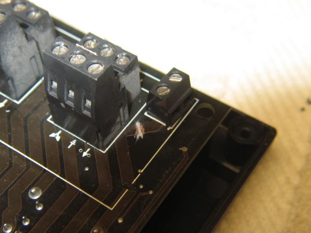
Try touching your hand to it when its not working and see if that gets it going. It may indeed be more of a signal problem.  Moving it to a different location or even just changing the angle may clear up the problem. 

This is absolutely the clearest answer to get the SC-2 up and running. I am new to legacy and this piece of gear. I spent a few days trying to get two sets of FasTrack remote switch crossover sets working. A lot of weird stuff. Finally, went with this configuration for power which simplified things. I was then able to check the terminals as a final rule out and discovered #2 was the cause of all of my problems. Well, I bought the SC-2's used and didn't pre-test them.

 
Originally Posted by Mike CT:

As John mentioned separating common track input on relay #1 seem to simplify things, at least for me.   I use the wall wart for power.  Each relay contact points set is then separate from the internal power common of the SC-2 (All (6) sets).  Note where the trace has been removed/interrupted between the first relay set of contacts, and the two terminal set, used, I believe, for accessory power input.  If it's working intermittent, in may be more of an issue of placement of the SC-2 related to TMCC signal.  It has to be relatively close to a TMCC signal source, i.e. track signal available to the units/locomotives. There is no direct TMCC signal connection to an SC-2 as there is for other TMCC switching devices. (Example TPC or ASC).  Some time ago, excepted procedure was to just not use the (1.) set of contacts, which still allowed for (5) set of independent contacts, more than most, IMO.    Lionel SC-2 reference manual.  Click on the underlined phrase to access.


I originally had issues getting a solid response with my SC-2s. I was using the SC-2 in all six positions with the COM trace cut. The fix for my signal problems was to connect the COM terminal to the outside rail of my track...the rail where the Legacy Base signal output is connected. I think the SC-2 is much like an engine. It has to have it's wheels on the outside rail and gets the other "half" of the signal from the air. In the case of the SC-2, it's "wheels" is the COM terminal. I am not using the wall chargers, but instead connected a CW-80 to them for power. The U terminal of the CW-80 is connected to the U terminal of the Legacy Base and also the COM terminal of the SC-2. I would imagine that either source of power is good as long as the COM terminal is connected to the U terminal of the Legacy Base. Give it a try...and also if your SC-2s are under the track somehow shielded from the airborne signal, a ground wire (connected to pin 5 of the DB9 on the Legacy Base) over the top of them will help restore the airborne signal to them.

Thanks cjack,

My problems , I thought, were with powering it. I was able to power it multiple ways and some not so good. I had it connected to C on my ZW-C. It seemed ok, but I found it didn't play well with FasTrack switches. I have an AC wall-wart an the one that came with it. After cutting the ground trace on aux gnd in to terminal 1, I found the included supply worked the best.

I kept getting the switches on terminal #2 firing when the layout was powered on. Something inside must have failed, because when I finally tested all of the other in 6 switch mode, they worked fine.


This one has been under the layout in various places and I have no signal issues. I did take note of the reception type issues and the ground plane solution for future reference.


Thank you, again.

Last edited by Moonman
Post

OGR Publishing, Inc., 1310 Eastside Centre Ct, Ste 6, Mountain Home, AR 72653
800-980-OGRR (6477)
www.ogaugerr.com

×
×
×
×
Link copied to your clipboard.
×
×