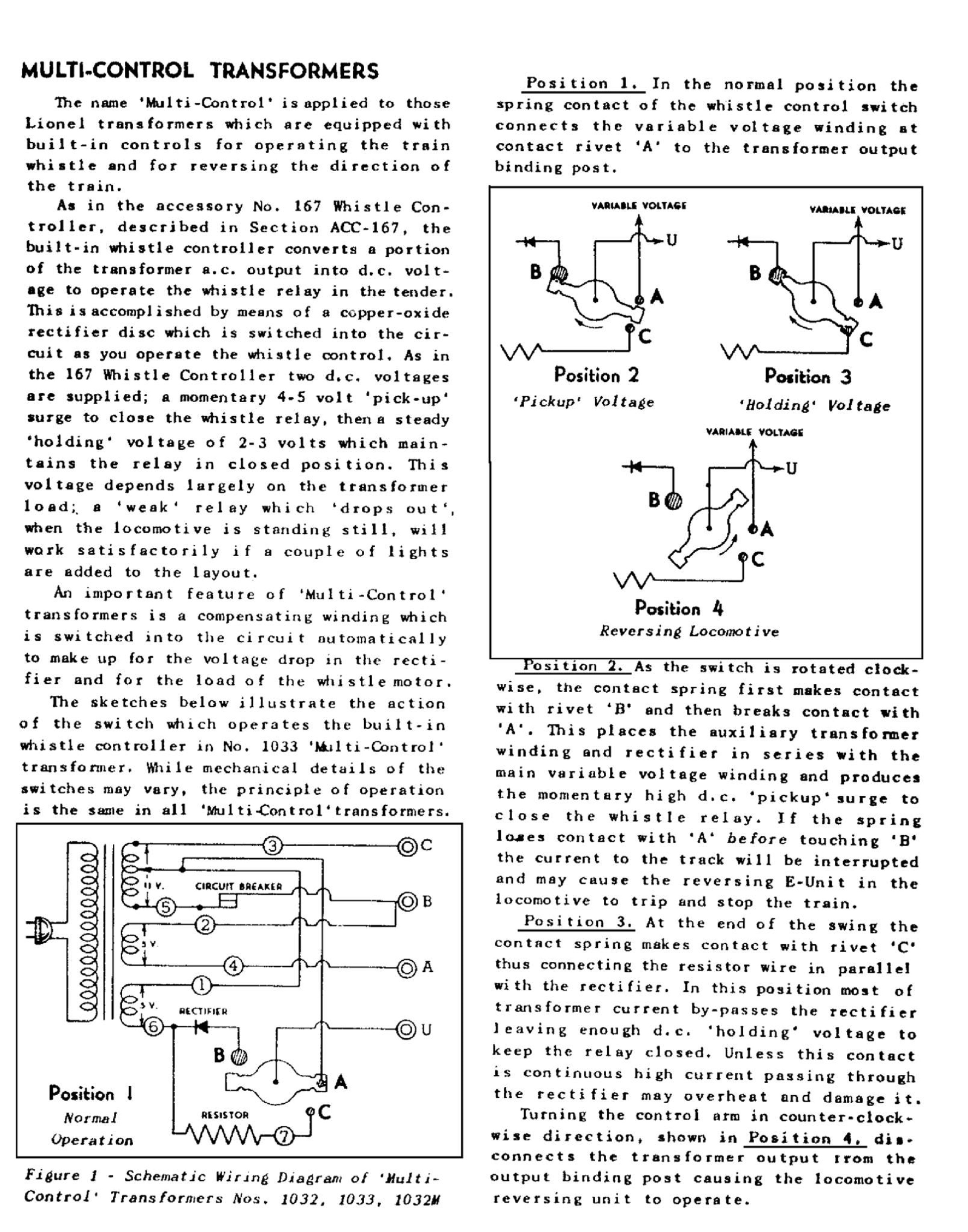
My ZW has a non-conducting wire covered with a protective sleeve going from the red pilot light to the U common post. Wire does not show conductivity when checked with a meter. I assume that it's a thermal or resistance wire. See attached picture.

Questions:

Did I fry the wire when soldering repairs and installing breaker?

What's the purpose of this type of wire?

Can I replace it with an 18 gauge wire?

Is there someplace that I can buy a replacement/substitution?

Do you have a wiring diagram for the ZW? Or did I miss it on this forum?

Attachments

Images (1)
  • WIRE with covering
Original Post

Replies sorted oldest to newest

As John says, these are resistors. The diagram calls them out at 1.5 ohms (Ω). I suspect Lionel put them in so the full amperage does not go through the rectifier when the whistle is activated. So if you put a meter across the ends of the wire, you should see ~1.5 Ω. (Do this with the power disconnected, or else you could fry your meter!) You do not want to substitute a piece of plain wire! That will become the path of least resistance and then your whistle will never work. If you need to replace the resistor, I'd recommend a heavy wattage power type, 1.5 Ω.


OOPS, me too!  But leave the 60Ω resistor in place. It keeps the bulb from frying.

Chris

LVHR

Last edited by lehighline

What I need to know how the ZW whistle side of it works. In particular the extra voltage circuit. On my ZW the right side doesn't maintain the voltage when uou blow the whistle. I have tried to adjust the copper contacts so they make contact but that foes nothing. What I need is direction. I want not to try to take this apart. Note that I installed a diode to replace the copper wafer about 8 years ago and has been problem until last week.

@Rich D posted:

What I need to know how the ZW whistle side of it works. In particular the extra voltage circuit. On my ZW the right side doesn't maintain the voltage when uou blow the whistle. I have tried to adjust the copper contacts so they make contact but that foes nothing. What I need is direction. I want not to try to take this apart. Note that I installed a diode to replace the copper wafer about 8 years ago and has been problem until last week.

I don't have any answer for you, but you may want to start your own separate thread, since your question has nothing to do with the topic or the previous discussion. other than involving a ZW transformer.

I mentioned this on another thread just a few moments ago.  Greenberg's Repair and Operating Manual for Lionel Trains, selling on Amazon for around $25 is a good investment to those running pre-war.  Explanation of  function from a crossing gate to a ZW is explained quite well, along with parts breakdown.  It is really a compilation of all the Lionel instruction sheets that came with various things, plus a lot more.  Many items include common problems and repair suggestions.

Last edited by CALNNC

Add Reply

Post
×
×
×
×
Link copied to your clipboard.
×
×