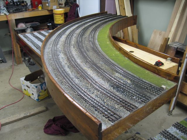
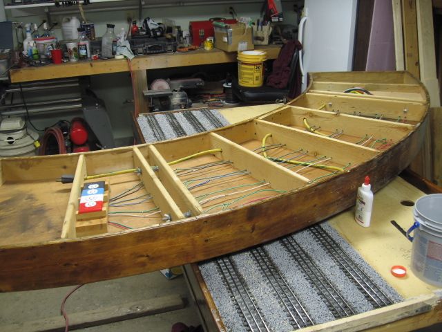
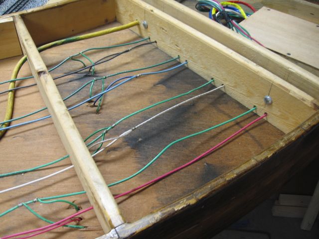
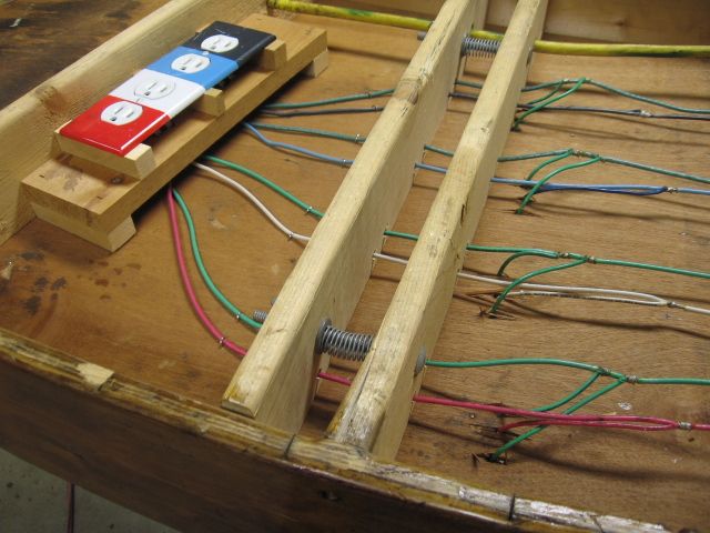
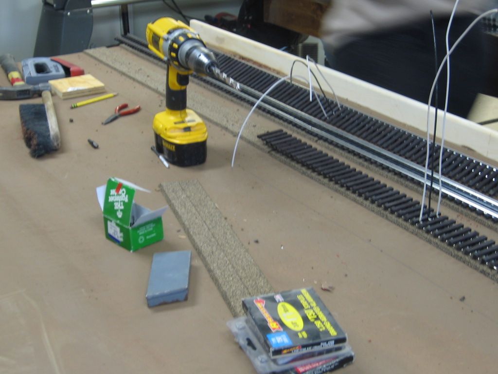
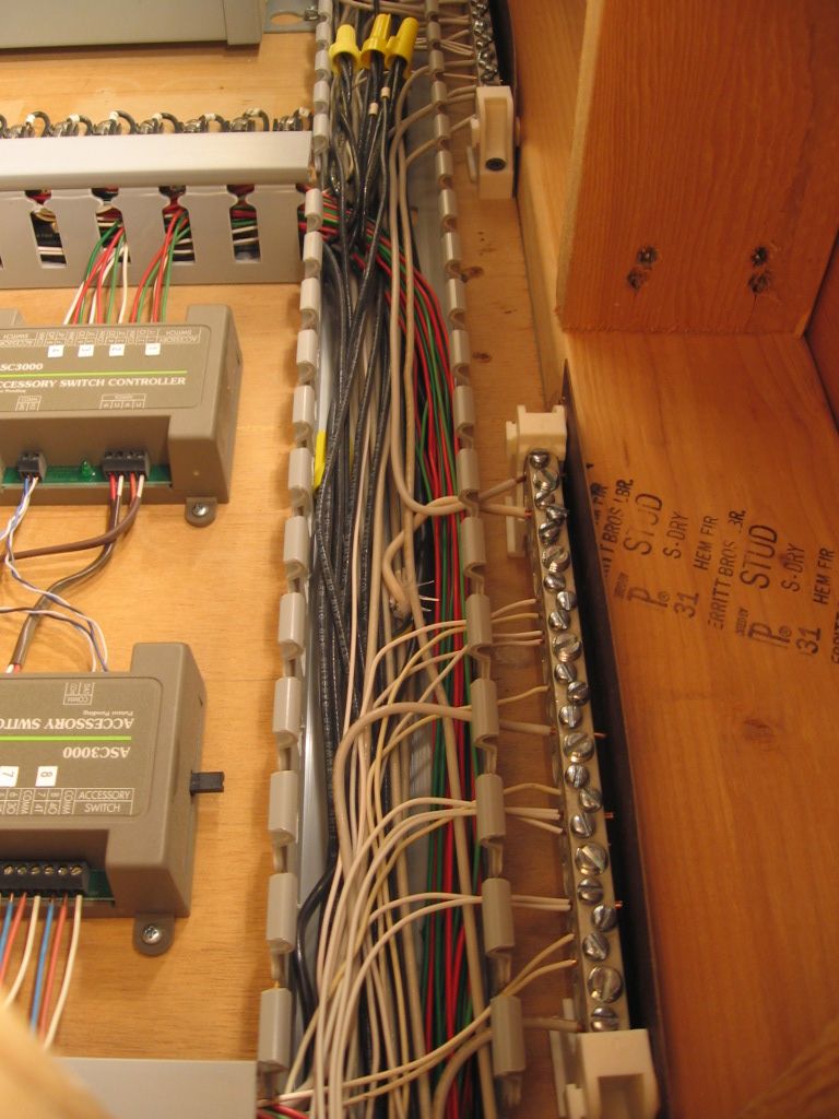
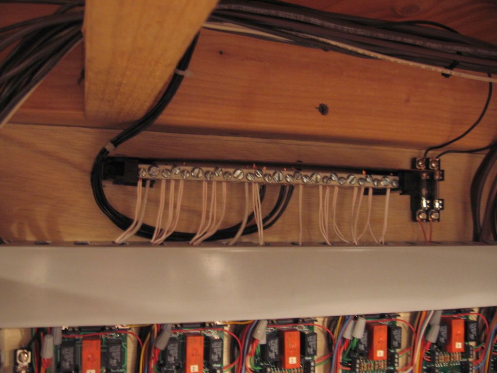
At the wiring phase of my layout which I am not really looking forward too. My question is what is the best size wire to use for power to the track, switches and accessories? My power is coming from 2 Lionel KW's if that makes a difference. Any suggestions would be greatly appreciated.


Thanks,


Bruce

Original Post

Replies sorted oldest to newest

I ran a bus wire of stranded 14 AWG with feeders of stranded 18 AWG as Lionel suggests.  I have no troubles along my 200' of track.  Auto zip wire is high grade wire and is red and black coded.  Here's where I got mine:


http://www.mcmelectronics.com


1

24-1880 - 250 Ft 16 AWG Automotive Zip Cord


$48.99


1

24-1870 - 100 Ft 18 AWG Automotive Zip Cord


$16.99


1

28-6082 - .080 Female Disconnect


$6.49


Originally Posted by bag09:
How do you connect your feeders to your bus wire?

I would recommend either:

  1. Barrier (or terminal) strips - 4 position.  Run the Red/Black pair to the center 2 positions and jumper the feeders to the outside poles respectively.  Use crimp-on spade connectors for all wires.  This might end up being more expensive but it has the advantage of easy disconnection.
  2. Suitcase connectors.  Buy them from an electrical supply house, otherwise you'll pay too much.


84109

George

Attachments

Images (1)
  • 84109

I went to Home Depot and bought rolls of 14 gauge wire.  I have two loops and used Red for one loops center rail and Orange for the other.  I used Black for both grounds.  I used FasTrack and attached the wire using the terminal connectors.  I dropped both wires through a hole and connected the wires to a terminal block.  I used a barrel connector to extend the wire to the terminal block.  I used a CMB4/10 terminal block.  This allowed 19 wires to connect from the track and one to connect to another block or to the transformer.  I did one loop at a time so I didn't get the ground wires mixed up.  I posted information about the CMB4 on another post.

This is from another posting.  Open the link and look at the picture.  This is what I used on my layout.  I attached a pair of wires to the fastrack using crimp on connectors.  I dropped the wires thru the layout and connected all the wires to a terminal block.  One for red and one for black.  I cut the wires about 4' long and as needed I lengthened the wires using a butt connector.  I added more wire drops to my layout then was really necessary.  I ended up using three sets of terminal blocks and connected each block together with a long wire and I then connected the terminal block to the transformer.   


I found these at this company. http://www.alliedelec.com/sear...il.aspx?SKU=70078316 I purchased the jumper and can connect on supply line and have 19 lines coming out. The CMB4 Terminal block can be assembled to any length you need. The jumpers are a little tricky to install, but I figured out how to do it quickly. CMB4-10 $6.55 10 slot Jumper $2.29. I bought ten of each.

Originally Posted by bag09:

     At the wiring phase of my layout which I am not really looking forward too. My question is what is the best size wire to use for power to the track, switches and accessories? My power is coming from 2 Lionel KW's if that makes a difference. Any suggestions would be greatly appreciated.


Thanks,


Bruce

What type of control are you going to use? TMCC/Legacy, DCS, Conventional or all combined? This could make a difference in how you wire your layout. DCS has some recommended wiring methods for DCS. Even if you don't have it now, you might someday and planning for it now may help you later on. Layout size would be another important consideration as well as track type you are using.


I used the wire sold by our very own forum providers, OGR, available on their website. #14 for the main feeds to MTH terminal blocks and then #16 from there on for the drops to the track. It is very nice wire.


If you are going to use terminal strips, you might want to look at the euro style terminal strips, they are very reasonably priced most places, you can cut them to any length and number of terminals you want and no crimp connectors are required.


Another consideration for switches and accessories would be #18 thermostat wire available from Home Depot, Lowes, Menards or other home improvement centers. It is available in 2, 3, 5, 7, 8 and possibly more conductors. I have been using 2 and 3 conductor for my Atlas switches and lighting. It is reasonably priced for multi-conductor wire. The possible dis-advantage is that it is solid wire. This is an advantage for me as you can make a loop at the end for connecting to the Atlas switches without using a crimp connector. Works well for the Atlas screw terminals on their switches.

I am using the conventional method with Lionel tubular track with American Flyer 3 rail switches. The switches have the option of regular operation or two train operation. My layout size is 6x12. Main part of layout has two separate ovals each with a passing siding. The inner oval also has one small spur. Have a small second level with a 3x6 oval. Hope that helps. I have 2 KW transformers. Planning on using one transformer for the two larger ovals with passing sidings and the other KW for upper loop and accessories and lights. Hope this helps. Thanks

Three questions you should figure out are:

  1. How long is the longest wire run?
  2. How much current will the wire carry?
  3. How much voltage drop can you tolerate?


Lets assume the longest run is 20 feet, you intend to run up to 10 Amps and you can tolerate a 1 Volt drop. From the wire table in the wikipedia link below, 14 gauge wire has a resistance of 2.525 ohms per 1000 feet, or 0.002525 ohms per foot. Since we have a feed and return wire (two wires) our total wire distance is 2 x 20 feet = 40 feet. Total resistance is 40 x 0.002525 ohms = 0.101 ohms. From ohms law we can calculate the voltage drop. V = I x R. Voltage drop = 10 Amps x 0.101 ohms = 1.01 Volt drop. Moving to a larger gauge size like 16 will increase the voltage drop due to less copper area (more resistance) of the wire. Moving to a smaller gauge size like 12 will decrease the voltage drop due to the larger copper area (less resistance) of the wire. It is also importance to buy wire that is rated to handle the voltage you are running through the wire. Its a good idea to stay away from low voltage wire (12V) intended for cars. Your trains run on around 20VAC with a peak voltage of around 28V. Buy wire with a rating higher than the peak voltage you plan to run (Peak voltage = AC Voltage x 1.414). One last thing to consider is to make sure you get stranded wire with a moderate strand count (solid wire is not very flexible).


Source for wire:

http://www.mcmaster.com/#stand...ctrical-wire/=u9o9fv


http://en.wikipedia.org/wiki/American_wire_gauge

http://en.wikipedia.org/wiki/Ohm%27s_law


I'd like to add another thing. All wire has a limit to how much current it can carry. Basically the current flowing through the wire times the voltage drop gives you the power dissipated on the wire in watts. This power dissipated heats the wire. The insulation on the wire also has an operating temperature rating of typically 105*C. The insulation is what prevents two wires of opposite polarity from shorting out and potentially causing a fire. Running excessive current through a wire can also cause a fire even without shorting out. So how much current should you run in a wire? Well you can Google "wire ampacity chart" and find various charts giving guidelines for a wires current carrying capability. I found a few different charts with different ratings on 14 gauge wire. This may be due to different standards used to calculate the data in the charts. Maybe someone else will chime in here?


While I'm rambling, poor connections at the ends of the wires create voltage drops and can melt things and even cause a fire. Be sure to crimp or solder your connections well. I'm sure you can find some good examples on Google.

Last edited by Matt A

Modular wiring, (Fort Pitt High Railers).   Red, White, Blue and Black are the (4) Track circuits (A).  Green wire is outside rail common (U). Note that both outside rails are connected with drops.   This module has (2) sets of drops from the track. Most (6ft) modules seem to work well with one set of drops.  We have upgraded modules by soldering jumpers across the track junctions to increase track conductivity.

Gargraves track with 14 ga. solid wire solder to the bottom of the rails before installation.

Last edited by Mike CT
Originally Posted by bag09:
I am using the conventional method with Lionel tubular track with American Flyer 3 rail switches. The switches have the option of regular operation or two train operation. My layout size is 6x12. Main part of layout has two separate ovals each with a passing siding. The inner oval also has one small spur. Have a small second level with a 3x6 oval. Hope that helps. I have 2 KW transformers. Planning on using one transformer for the two larger ovals with passing sidings and the other KW for upper loop and accessories and lights. Hope this helps. Thanks

I think you would be fine with #14 bus wiring as shown in Volphin's diagram above and #16 or #18 for your drops to the track. As I understand the KW's (I am not real familiar with them) they are 190 watt for 2 trains so I would guess you would be using half of the one for each larger oval and passing siding, or about 5-6 amps or so for each loop, and the other about the same only with some going to accessories.


The OGR wire is very nice, I really like it and use it on my layout, but if you use the suitcase connectors shown in G3750's post it could be difficult to remove the outer jacket to get to the wires you need to splice into for the track drops. The terminal strips would be better suited for the OGR wire. Single conductor wire (1 each, red & black) would probably be better for use with the suitcase connectors.


I personally like the euro style terminal strips, that's what I use on my layout. Here are some 10 amp euro style terminal strips on ebay, similar to what I have. Got most of mine at Radio Shack a couple years ago, they were closing out that particular model and they were pretty cheap. RS still has them but a different brand or something


I am not at all familiar with the American Flyer 3 rail switches either. I would imagine the thermostat wire would still work for them, however it is solid wire. I don't know what kind of terminals are on those switches? I am using terminal strips on most everything but my switches, they are wired directly. 


I am using the thermostat wire for accessories and lighting (just about everything but track power) on my layout. I started out to use #18 or #20 stranded wire in 2, 3 and maybe 4 conductor (my preferred type), similar to the OGR wire, but it was difficult to find and most of it was shielded and more expensive than the t'stat wire. The t'stat wire was also readily available for me locally at Lowes & Home Depot. No shipping and handy, I can just go get more if I need it.


Last edited by rtr12

A terminal strip is used to connect a bunch of wires together without twisting all the ends together.  This is the strip that I used.  All of the wire slots along the sides are connecter together with a jumper that goes in the slot in the middle.  A two hole jumper is shown below.  This terminal strip has 20 openings, with a screw that tightens the wire in place. If you connect one wire from your transformer hot wire it adds power to the whole strip.  Now there is room to connect 19 additional power wires to your track center rail.  You need another terminal strip connected to the outside ground rails. 

cmb4-10

jumper

Attachments

Images (2)
  • cmb4-10: Thes are available from 2 to 100 pairs.
  • jumper: These are avalible from 2 to 10 and a strip of 100 for custom lengths.
Originally Posted by jmiller320:

Here are a few other types.  The top is the Euro Style, next is a type that is available in most big box stores.  Both types need a jumper or wires connected to each terminal.  The bottom is a MTH terminal that holds 24 wires.  One side for red and the other for black.

Eurostyle

terminal strip

mth terminal

Jmiller's photos should be very helpful.


The Euro style terminal strips are useful for those applications where you are not jumpering connections - like accessories.  At least that's what I use them for.  I favor the more traditional strips in the second photo (used with crimp connectors).  They are inexpensive, readily available from multiple sources, available in many sizes (2 position to 24) and can be easily jumpered using the following:


terminal strip jumper

The MTH item is convenient but expensive for the capabilities provided (you're paying for the name, IMO.).


George

Attachments

Images (1)
  • terminal strip jumper

Add Reply

Post
×
×
×
×
Link copied to your clipboard.
×
×