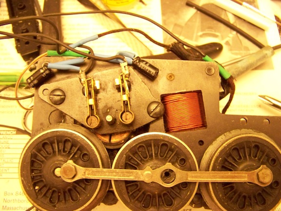
I'm getting ready to install the ERR AC Commander in a pair of traditional spur-geared steam locos.  I'm intending to place the antenna and circuit board in the tender shell, and run a multi-wire tether back to the loco for motor power.  


The instructions call for snubber capacitors to be connected across the motor brushes.  The illustrations suggest a Berkshire type motor or diesel.  Has anyone here installed one of these in a Postwar 2046, 2037, 675, 1615, etc.?  If you have I would LOVE to see some pics of the assembly, especially your brush plate side with the capacitors.  Were you satisfied with the operation?  Any advice is most welcome!  Thanks!!

Original Post

Replies sorted oldest to newest

I'm working on one right now.  It's actually a rework.  I'll post photo's of the caps installed on the spur gear frame this evening.  These are actually from an LCRU kit from Digital dynamics.  I'm replacing the LCRU in the tender with an ERR AC commander since the LCRU no longer works in command mode.

Thanks all, especially Chuck for posting a nice pic!  

John, how did you work around the protruding armature shaft?  Are they visible when the boiler shell is on?

Also- were you satisfied with the performance afterward?  Is there a decent slow speed, and do you experience any loss of signal because of the AC sparking?

Thanks again for your insight and willingness to share.  -Ted

Where you see the capacitors, I just have them folded down on the outside of the brush holders, I didn't put them inside next to the shaft. Where Chuck shows them is fine, you just need to keep them out of the line of fire when you put it all back together.  It's best to keep the leads as short as possible.


The caps are there to suppress the excess sparking from the brushes and do a pretty good job.  As far as low speed performance is concerned, it's still an old PW AC motor, so it's not going to knock your socks off.

Post
×
×
×
×
Link copied to your clipboard.
×
×