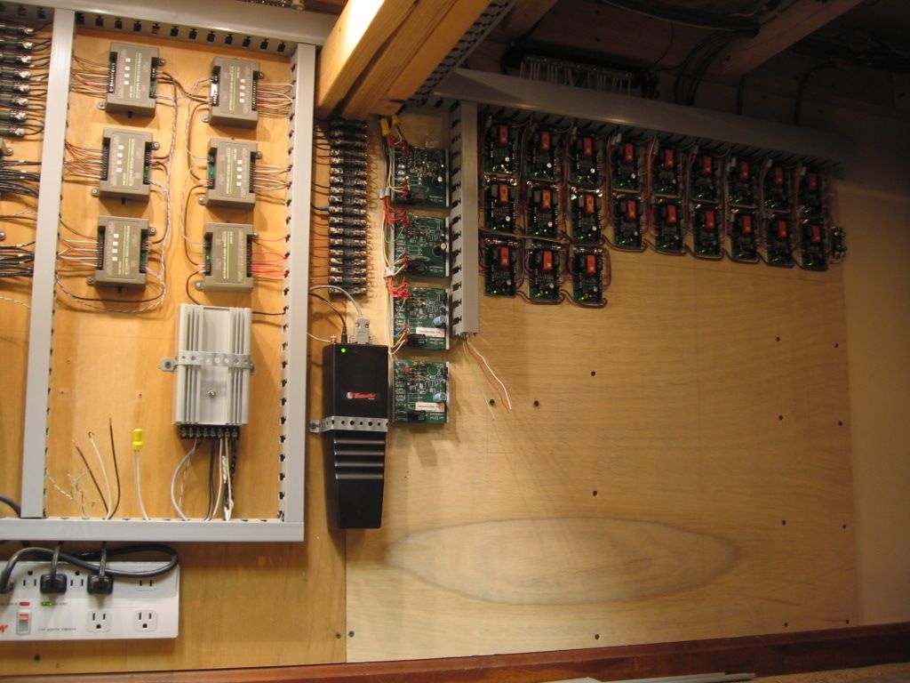
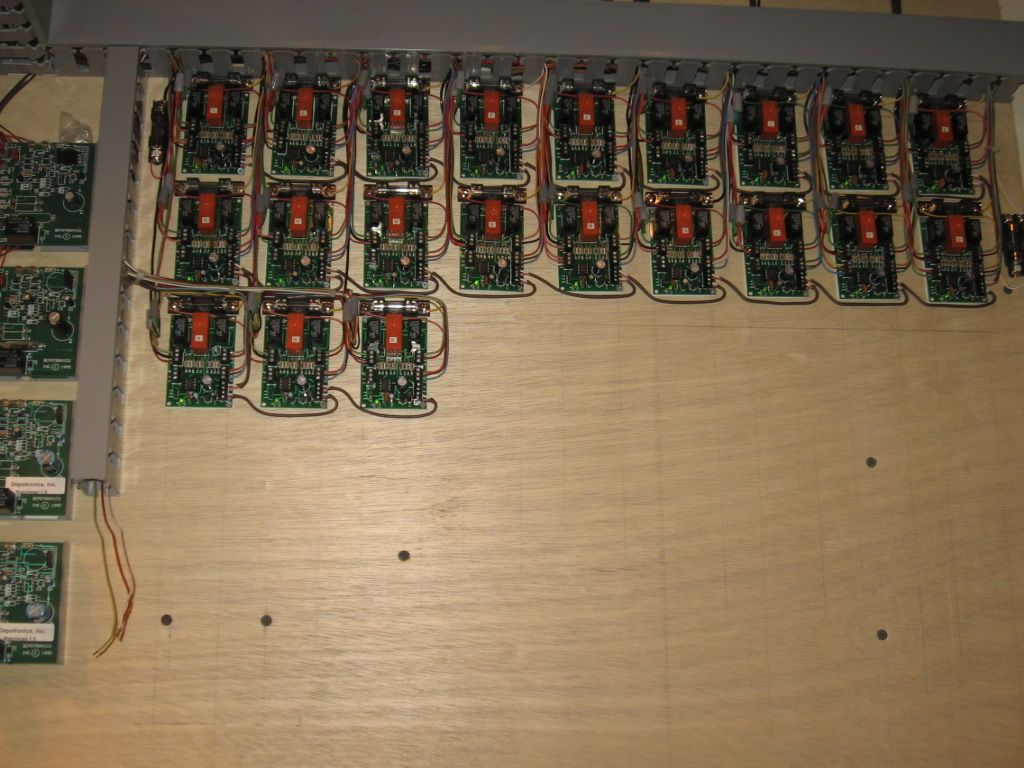
Hey, I'm a convential kind of guy.  No fancy"chip based" stuff for me.  Just a simple mimic panel with a toggle for each switch and block and siding power.


WRONG!  My simple convential panel has turned into a Dale H. nightmare.


Only one of six panels and I haven't even started on the uncouplers yet.

OK a little late on a 'timely' post on this subject, but I'm buildin and just finalized my panel design.


So JIC anybody goes searching, I'd like to show what I came up with.  I think it fits my bill pretty well, and has the 'feel' of prototype + O-gauge + simplicity ...


I had a couple considerations to factor in.

1.  I wanted 2 cab control

2.  It needs to be informative, and easy to understand

3.  Simple enough for a 3 yr old (grandsons) to operate

4.  Big enough for those with 'all thumbs' and/or 'aging eyes' to easily operate


So here's the panel (less most hardware)

Panel_Gen-NoHW

Panel is 24"w x 12"h.  Switch controls have a silver 'box' to help group things clearly (but cleanly)


Panel_Buttons

Crossover Switch control and indications.  There will be 2 green leds and a yellow when the switch is on crossover position.


The Standard switches are simple red/green buttons and leds.  Because of the way the lionel fastrack switches work, there can be multiple panles/indicators for each switch, and when Legacy/TMCC comes in to play the panel(s) will by default follow all switch activity.


Block control will be with a standard heavy duty SPDT-center off Toggle switches (block breaks currently not shown, I need to add to the art.


Switches installed

Populated Panel


I guess Im kinda doing a progress post at this point

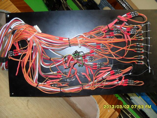
Panel Wiring

Just a bit of wiring, I used 22/4 stranded wire (alarm cable / stranded telephone wire) and labeled the heck out of everything

I also made it about 6 feet longer than I needed, so I had plenty of 'service loop' and I can relocate it just about anywhere around the island it is on ....

IMAG0932

Not a great shot, but up and running (still have a few sidings to contend with tho)

I decided to add some mini toggles later for uncoupler control ....


Attachments

Images (5)
  • Panel_Gen-NoHW
  • Panel_Buttons
  • Populated Panel
  • Panel Wiring
  • Installed Panel
Last edited by PeteF
Hugh; What is the source of that multi strand gray cable you used? I could sure use some.Originally Posted by Hugh Laubis:

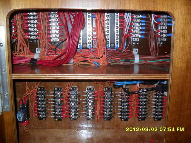
I built my train table on top of kitchen cabinets.

I built my control cabinet in a modified 'sink base'

Two pictures are enclosed, one of the bottom which contains lots of horsepower and the top which contains the panel.

This rolls in and out when necessary with a set of cables from the rear to stationary panels to prevent wires from breaking.

This is all still part of my layout, however there is nothing in that panel which I now CANNOT run directly from my DCS handheld.

If I were starting from scratch, I would bury all transformer power and run all my Conventional, DCS and TMCC from my handheld as I do now.

I built this for my HO layout over 30 years ago and am still using it. It's a basic dual-cab control with center-off DPDT toggles on a pin-stripe track diagram for the major portion of the layout. The green-handle toggles are for reverse loop blocks and reversing switches (DC power for HO).


HO control panel

Attachments

Images (1)
  • HO control panel

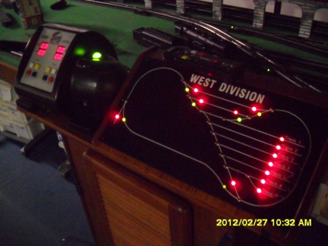
Besides a single layout 'power on' switch and my 'MTH DCS Handheld' there are no other visable aids to running the layout except these wall mounted panels with LED's to tell me the status of what is going under my 'Mountain'. and in my 'closet tunnel'.


Click on pictures to enlarge them.


100_5236 [1024x767) [640x479)


100_5237 [640x479)


My mountain can be seen here.

http://www.jcstudiosinc.com/BlogShowThread?id=958&categoryId=


 More on LED's

http://www.jcstudiosinc.com/BlogShowThread?id=896

Attachments

Images (2)
  • 100_5236 (1024x767) (640x479)
  • 100_5237 (640x479)
Last edited by Hugh Laubis
Originally Posted by trainman129:
Hugh; What is the source of that multi strand gray cable you used? I could sure use some.Originally Posted by Hugh Laubis:

I built my train table on top of kitchen cabinets.

I built my control cabinet in a modified 'sink base'

Two pictures are enclosed, one of the bottom which contains lots of horsepower and the top which contains the panel.

This rolls in and out when necessary with a set of cables from the rear to stationary panels to prevent wires from breaking.

This is all still part of my layout, however there is nothing in that panel which I now CANNOT run directly from my DCS handheld.

If I were starting from scratch, I would bury all transformer power and run all my Conventional, DCS and TMCC from my handheld as I do now.

Wow! That post was one year ago!  ..... and ..... I just made an additional one a few minutes ago not realizing it was the same thread.


Those cables were used to tie the backside of the sinkbase which contained all the power and switches etc. to the permanent part of the layout. This allowed me to pull away the sinkbase and access the underside of the layout. This is redundant effort unless you have no other way to get under your layout. This was true in my old house but no longer needed and sink base rarely if ever gets moved any more.

But to answer your question, they were interface cables from old IBM 370 large scale computers that I picked up at an electrical supply house in Roanoke. They were used, I knew what they were, I wanted them, and they were cheap!

I doubt you will find them anymore.

Originally Posted by Kerrigan:

Here is a panel that I did, that is 42" wide by 14" high.


Jim

DSC_0032

Jim,


That is a Cool control panel!  You did an incredible job on the panel layout!  I really like the decals with RR names.  Where did you get those?  I would like to do the same thing (UP, SF, CAT, PRR, CSX) decals if I can squeeze them in on my mini control panel.

Kerrigan - The mini toggle switches that I use in my panels are from Radio Shack and the part number is #275-324.  These switches are rated for 125V at 10A and are very small and they work just fine for DCS and TMCC/Legacy layouts. 

litegide24 - I had described the process for building this panel on the first page of this same thread.  The logos were copied from the internet or designed from a picture by myself.

Thanks for the positive comments on this panel.  You can view more detailed pictures here http://www.jcstudiosinc.com/Bl...=533&categoryId=

Originally Posted by hojack:
Yikes.
Got some track down and one of these days I have to start running some wires.  Hugh, your 6 photos from Feb 2 are beautiful but scare the bejeekers out of me.
I am planning for DCS.  A few questions for the wiring gurus:

1) Hugh, "If I were starting from scratch, I would bury all transformer power..."
If I leave the handles on my Z4000 up when I power it off, then when I power back up it outputs garbage and I have to cycle the handles down and back up by hand to starighten it out.  Is this just me, or do I have to have my Z4000's out on a shelf where i can get to them every time i power up? is there some way around this? The outlets in the train room are controlled by a relay, with one wall switch by the door so when I leave I know everything is off, and everything can come on with one switch when I come in. Except for the z4000's?

2) Hugh, " ...run all my Conventional, DCS and TMCC from my handheld as I do now."
and rrman, ""I don't need no stink'in control panel, they're all in my DCS handheld!!"
My previous layout had a large panel with switches and LEDs, but then I saw the (DCS) light and I never looked back."
I know this is how DCS is designed and works, but are you guys seriously saying that you throw all your turnouts by scolling around on that handheld instead of just toggling a switch on a schematic panel?  I just can't imagine it would be anywhere near as convenient.  If so, then great! no need to build a control panel.  But it seems like you gotta push a lot of buttons to get to a turnout on the hand held?

3) this will really show my ignorance, but both Hugh and ChoCho Bob look like you're using the long white telephone punch-down terminal blocks.  Can't see from the photos what wires you are running to them and can't think why you'd have so many wires going to one block unless... are you using these for your commons?

thanks

Hojack,


The Z-4000s are designed to require their handles be cycled when the power is cycled.  So yeah, you have to have them where they can be reached.  That's one reason I replaced mine with Lionel 180 watt PowerHouse bricks.  Much cheaper, too.


I don't run DCS, but I do have TMCC.  The problem is the same with either or any remote.  How fast can you throw a switch using a sequence of scrolls or keys?  I can throw my switches using my CAB-1 remote, but I have pushbuttons installed in the fascia under each switch.  That way I can walk around and throw switches quickly when necessary.  It's a good compromise, in my opinion.


I do not have a control panel.  However, I do have two power distribution panels - each of which serves 4 power districts.  Each district has a bulb to indicate when power is flowing to it.


George

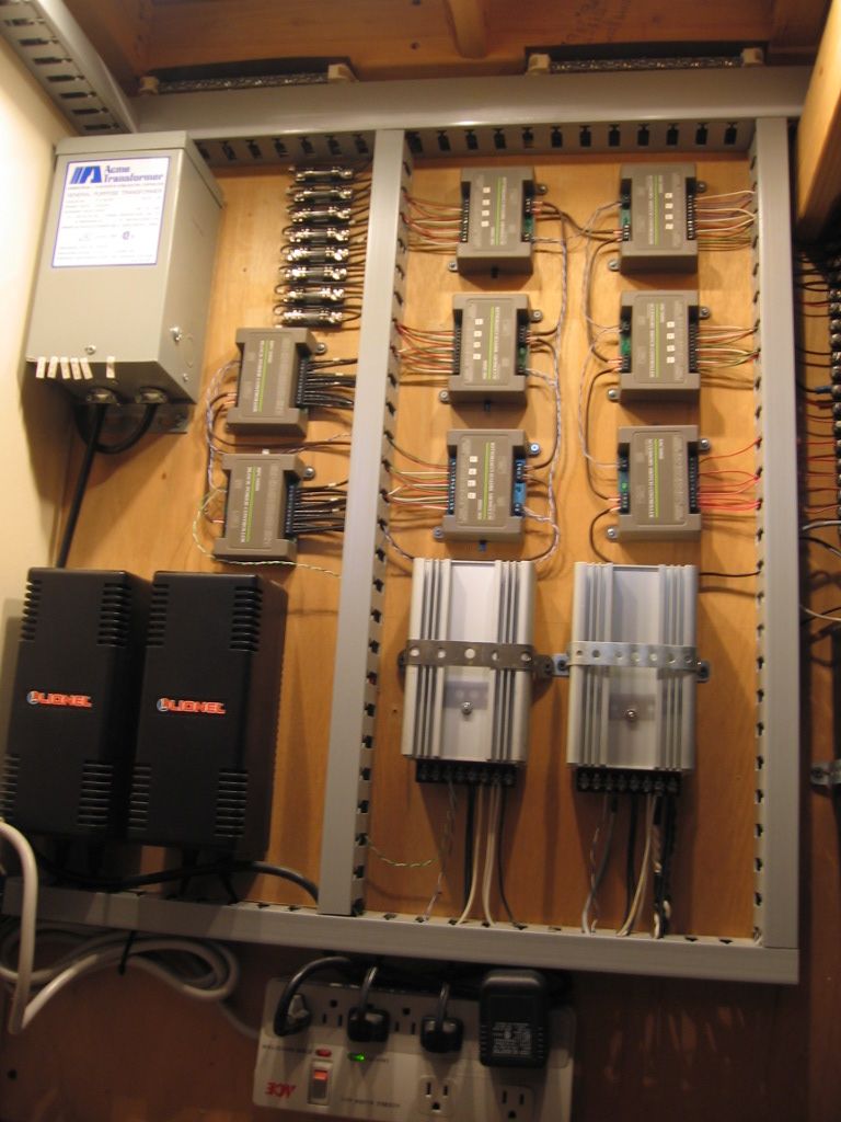
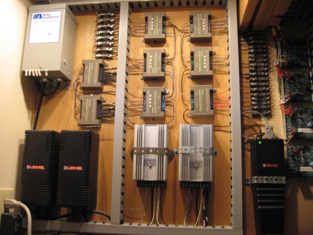
The pictures show a model railroad Patch Board specifically designed for use with two MTH model 50-1004 Accessory Interface Units and the MTH 50-1001 DCS system. This patch board provides for easy connections for up to 40 control circuits per board. The Patch Board features convenient screw terminal blocks which provide for a total of 120 individual wiring connections.


patch panel 2


Attachments

Images (1)
  • patch panel 2
Last edited by pro hobby


Note: The MTH model 50-1004 AIU provides 10 control relay outputs designed for activating turnouts and another 10 general purpose relay outputs. The AIU general purpose relays can be used for operating various accessories or for block control when routing trains. The terminal strips are colored coded and individually numbered for ease of use. All wiring (not shown) when completed ensures that wiring errors for connections to the layout are minimized.

patch panel 1

Attachments

Images (1)
  • patch panel 1: Supports two MTH AIU controllers

The model railroad patch board is completely portable and modular. The patch board is able to be easily connected to other modules which include:


1: Turnout control module that uses 12 volt relays to operate MTH turnouts (switches).


2: Block Control module that uses 12 volt relays to provide block signals to the various blocks on the layout.


3: Source Control module that connects to either the fixed or variable outputs from the MTH TIU.


4: Accessory Control module that connects to various operating accessories on the layout.


Note 1: All wiring is completely color coded and labelled by function.


Note 2: A separate Dispatcher Center (not shown) displays the status of all turnouts and blocks. Various colored LEDs are mounted on a 1/16th scale representation of the layout plan. 


Note 3: The Dispatcher Center only provides status. All control is provided by the MTH Hand Held remote controller system. (MTH 50-1001).


Note 4: All interconnections between modules are made using prefabricated wiring harnesses. This makes troubleshooting and upgrades very easy. 


Note 5: All wiring is shown on individual CAD drawings made on a computer using Visio software and then paper print copies are place in a folder for reference.

This was built by AGHR member Frank Davis to control the turnouts in the harbor. It uses bi-color LEDs to indicate routing. Here's a preliminary test before we set the other LEDs. This is one of the nice features of Tortoise machines -- they have an internal resistance of 600 ohms so you can hook LEDs in series with them.

Harbor_Control_Panel


Here it is in normal operation:

2013-04-17 18.54.11

Attachments

Images (2)
  • Harbor_Control_Panel
  • 2013-04-17 18.54.11
Last edited by AGHRMatt

Add Reply

Post
×
×
×
×
Link copied to your clipboard.
×
×