
Have seen a few photos of control panels and looking for more ideas.
For toggle switches could i use regular wall switches (110)? i like the feel of a big switch.
Original Post
|
|
Replies sorted oldest to newest
quote:For toggle switches could I use regular wall switches?
Okay here's mine. I used SP switches from Radio Shack though I'd like something heavier.
Here is one I just finished. Using Toggle switches from Home Depot. ON/OFF/ON.


Here is what I am working on for the Hidden Pass Junction RR. The panel itself is complete other than I have to add (insert from behind) the LED's at each turnout. The panel is 18" x 36", and I am working on the wiring now.

I'll post more pictures later today or tomorrow under a separate thread. (I am just testing the new forum posting ![]() )
)
Alex


This is mine ,
The black strip in front of the transformers is for operating accessories .
All my switch activation buttons are in the schematic and signal a building light switches are to the side.
Everything is hinged for easy access.
I think it turned out pretty good for a Half *ssed carpenter like me.
David
"Old School":

Here is one my brother and I built. Paper between two layers of Acrylic.


"Old School":
Wow---proving once again that there is nothing like the old stuff for sheer impressiveness!


Here is a panel that I did, that is 42" wide by 14" high.
Jim

Jim
Great looking panel. Can you please describe what materials were used, lettering , graphics, etc. I need to build 4 panels ( 3 levels plus a yard area)
Thanks
Tony
I built my train table on top of kitchen cabinets.
I built my control cabinet in a modified 'sink base'
Two pictures are enclosed, one of the bottom which contains lots of horsepower and the top which contains the panel.
This rolls in and out when necessary with a set of cables from the rear to stationary panels to prevent wires from breaking.
This is all still part of my layout, however there is nothing in that panel which I now CANNOT run directly from my DCS handheld.
If I were starting from scratch, I would bury all transformer power and run all my Conventional, DCS and TMCC from my handheld as I do now.


"I don't need no stink'in control panel, they're all in my DCS handheld!!"
My previous layout had a large panel with switches and LEDs, but then I saw the (DCS) light and I never looked back. ![]()
Here is my new panel after my DCS installation. Light switch at the right end powers up all the transformer power needed for my layout. The other two switches turn my (1)lighting (2) signal circuits on/off. Still have room for one more switch, but cannot figure out what for?
All the best,
Hugh

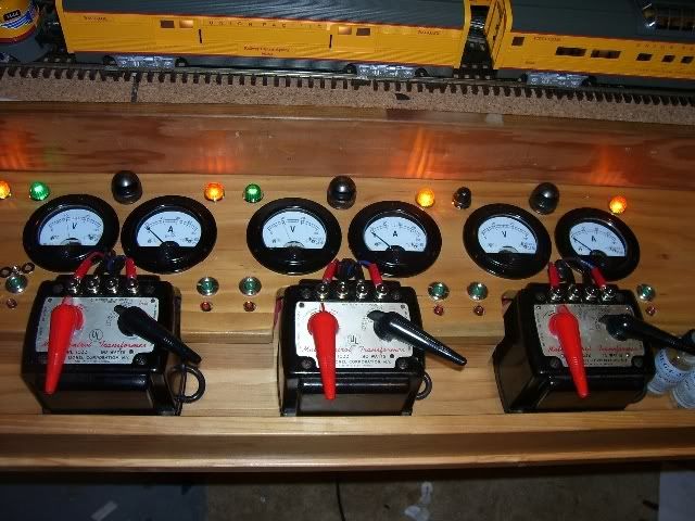
For a combination of nostalgia and WOW Factor, can't beat this one. This is not mine, made by a fellow who used to post here - Bobby Ding:
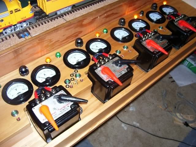
And look at the expression on that young man's face as he drives his train the old fashioned way. You don't get that kind of satisfaction from pushing buttons on a TV remote... unless it is a TV remote and you're pulling up an Anita Ekberg movie on TCM.![]()
Pete
Thanks for everyones posting and photos, great ideas here. I dont have any plans for DCS, prefering the older style "hands on" approach.
What are all those big "toggle" switches in the photo with the young boy and where to buy those?
Really like those volt and amp gauges, looks so cool. Are these practical for a train layout?
What are all those big "toggle" switches in the photo with the young boy and where to buy those?
Those switches are a row of 1122c controllers for 1122/1122E remote control switches.

My panel was designed on the computer. All of the RR logos were designed by me or copied from the internet. Before I print them, the original design is converted so that all of the little lights and switches that are seen on the drawing become little hash marks or crosses. This makes it clear as to where drill all of the holes precisely. It is then sent out to the printer, such as Kinko's or OfficeMax, to be print on a high resolution color laser printer. Once printed, it is laminated, trimmed and mounted on very thin plate steel to give it rigidity and strength. Holes are drilled and devices mounted, wired, and tested. The frame is installed and finished to the customers specs. All of the wiring is finallized through the back cover and landed on marked and labeled terminal strips for easy hook-up to the layout.
New school.![]()
New school.![]()
I'm a big believer in form following function, so if those panels work properly for their owners I'm down with that. But man their appearance is incredibly boring compared to old school. Hands down the best panel so far is BobbyDing's. There's just no accounting for taste, eh. ![]()
![]()
Pete
Here is my panel for 60 switches, 60 accessories and 27 blocks.


This is my power panel for my layout. I will be adding some amp meters later on.
Very nicely laid out.
Not really, just push SW on handheld and scroll to turnout (or punch number key) and press normal or diverging icon. Saves having to walk to panel each time to flip switch. Handheld allows up close operation and if turnout didn't throw or some obstruction you can stop train before consequenses.
The guys in our HO group are a tad extreme, don't you think? The control panel here shows the layout in paper, but is being done in engraved panels. It's probably been finished since I took this pic.

Not really, just push SW on handheld and scroll to turnout... Handheld allows up close operation
Point taken. thank you. no control panel. wait while i wrap my head around this.
The other thing would be toggles for all the sidings. Since I am doing standard gauge tinplate, the aesthetic calls for the knife switches like on the 439 panel or the switch tower buildings. Are these knife switches satisfactory to use with DCS or should I use new toggles? Does DCS signal degrade through the knife switches?
When designing my new layout I first had the idea to have no control panel as I plan to run 100% command control with my Legacy controller. After much thought I knew I would want yo reach over an flip a switch or two. I'm sure glad I decided to build the panel!
Most all toggle switches, terminal strips, wiring supplies and LEDs came from Demar Electronics. Great company to deal with. They had just what I needed and were helpful to make sure I ordered what I really wanted.
I wanted the panel below table top so to not interfere with a view of the trains. I also wanted easy access to wires. The panel opens from the center to make wiring easy.

All of my switch tracks, Ross with DZ 2500s and K-line Super Snaps are controlled by either SC-1s or SC-2s

Rather than have a jumble of wires at the back of the control panel, I built a "power distribution" center and it has worked out very well.


Transformers are neatly arranged below table and are easilly reached to turn up power on the ZWs which serve the five power districts. The KWs power accessories.
Stan
All controlled with a Cab-1. There are (2) BPC (Block Power Controllers) controlling (8) power districts. (1) TPC (Track Power Controller) that turns it all on an off. and (6)ASC's (Accessory Switch Controllers) (5) controlling 20 switches and (1) controlling 8 accessories.
This is my setup. I jumped on board with the controllers early. It's just the way I started. Most of my controllers are original IC Controls boxes. I love it. Been working great for 8/9 years. 3 bricks for power//-2 TPCs-1 for TMCC-1 for conventional operation//-2 BPCs-can switch 8 blocks of track from TMCC to conv//-4 ASCs-3 for 12 switches-1 for accessories//- 2 OTCs-1 for 4 Uncouple tracks-1 for 2 operating tracks//- 2 AMCs-1 to run log loader and lights on layout-1 for magnetic crane and light in blacksmith shop- (voltage outputs are adjustable on AMC-great for fine tuning power to tricky accessories)//-1 ARC-for recordings-works awesome// Command Base// Accessory power pack//Cab 1s to make it all go-all is operated by the Cab 1 remote


My panel to date........still a number of items to wire in yet.
REV

Hey, I'm a convential kind of guy. No fancy"chip based" stuff for me. Just a simple mimic panel with a toggle for each switch and block and siding power.
WRONG! My simple convential panel has turned into a Dale H. nightmare.
Only one of six panels and I haven't even started on the uncouplers yet.
OK a little late on a 'timely' post on this subject, but I'm buildin and just finalized my panel design.
So JIC anybody goes searching, I'd like to show what I came up with. I think it fits my bill pretty well, and has the 'feel' of prototype + O-gauge + simplicity ...
I had a couple considerations to factor in.
1. I wanted 2 cab control
2. It needs to be informative, and easy to understand
3. Simple enough for a 3 yr old (grandsons) to operate
4. Big enough for those with 'all thumbs' and/or 'aging eyes' to easily operate
So here's the panel (less most hardware)

Panel is 24"w x 12"h. Switch controls have a silver 'box' to help group things clearly (but cleanly)

Crossover Switch control and indications. There will be 2 green leds and a yellow when the switch is on crossover position.
The Standard switches are simple red/green buttons and leds. Because of the way the lionel fastrack switches work, there can be multiple panles/indicators for each switch, and when Legacy/TMCC comes in to play the panel(s) will by default follow all switch activity.
Block control will be with a standard heavy duty SPDT-center off Toggle switches (block breaks currently not shown, I need to add to the art.
Switches installed

I guess Im kinda doing a progress post at this point

Just a bit of wiring, I used 22/4 stranded wire (alarm cable / stranded telephone wire) and labeled the heck out of everything
I also made it about 6 feet longer than I needed, so I had plenty of 'service loop' and I can relocate it just about anywhere around the island it is on ....

Not a great shot, but up and running (still have a few sidings to contend with tho)
I decided to add some mini toggles later for uncoupler control ....

here`s mine


I built my train table on top of kitchen cabinets.
I built my control cabinet in a modified 'sink base'
Two pictures are enclosed, one of the bottom which contains lots of horsepower and the top which contains the panel.
This rolls in and out when necessary with a set of cables from the rear to stationary panels to prevent wires from breaking.
This is all still part of my layout, however there is nothing in that panel which I now CANNOT run directly from my DCS handheld.
If I were starting from scratch, I would bury all transformer power and run all my Conventional, DCS and TMCC from my handheld as I do now.
I built this for my HO layout over 30 years ago and am still using it. It's a basic dual-cab control with center-off DPDT toggles on a pin-stripe track diagram for the major portion of the layout. The green-handle toggles are for reverse loop blocks and reversing switches (DC power for HO).


Besides a single layout 'power on' switch and my 'MTH DCS Handheld' there are no other visable aids to running the layout except these wall mounted panels with LED's to tell me the status of what is going under my 'Mountain'. and in my 'closet tunnel'.
Click on pictures to enlarge them.
 (640x479)")
")
My mountain can be seen here.
http://www.jcstudiosinc.com/BlogShowThread?id=958&categoryId=
More on LED's
 (640x479)")
")
I built my train table on top of kitchen cabinets.
I built my control cabinet in a modified 'sink base'
Two pictures are enclosed, one of the bottom which contains lots of horsepower and the top which contains the panel.
This rolls in and out when necessary with a set of cables from the rear to stationary panels to prevent wires from breaking.
This is all still part of my layout, however there is nothing in that panel which I now CANNOT run directly from my DCS handheld.
If I were starting from scratch, I would bury all transformer power and run all my Conventional, DCS and TMCC from my handheld as I do now.
Wow! That post was one year ago! ..... and ..... I just made an additional one a few minutes ago not realizing it was the same thread.
Those cables were used to tie the backside of the sinkbase which contained all the power and switches etc. to the permanent part of the layout. This allowed me to pull away the sinkbase and access the underside of the layout. This is redundant effort unless you have no other way to get under your layout. This was true in my old house but no longer needed and sink base rarely if ever gets moved any more.
But to answer your question, they were interface cables from old IBM 370 large scale computers that I picked up at an electrical supply house in Roanoke. They were used, I knew what they were, I wanted them, and they were cheap!
I doubt you will find them anymore.


OK so you don't need a control panel anymore.But they are cool as H to have!
Mine is an out-of control panel ....
Here is a panel that I did, that is 42" wide by 14" high.
Jim
Here is a panel that I did, that is 42" wide by 14" high.
Jim
Jim,
That is a Cool control panel! You did an incredible job on the panel layout! I really like the decals with RR names. Where did you get those? I would like to do the same thing (UP, SF, CAT, PRR, CSX) decals if I can squeeze them in on my mini control panel.
Kerrigan - The mini toggle switches that I use in my panels are from Radio Shack and the part number is #275-324. These switches are rated for 125V at 10A and are very small and they work just fine for DCS and TMCC/Legacy layouts.
litegide24 - I had described the process for building this panel on the first page of this same thread. The logos were copied from the internet or designed from a picture by myself.
Thanks for the positive comments on this panel. You can view more detailed pictures here http://www.jcstudiosinc.com/Bl...=533&categoryId=
Here is my panel. Amp meters were added to the right later on.
")
")
")
")
Small, simple and cheap. Two mainlines and Yard of Service Towers with Engine House.
Only two power districts. Tortoise turnout motors.


Small, simple and cheap. Two mainlines and Yard of Service Towers with Engine House.
Only two power districts. Tortoise turnout motors.
Where do the drain pipes go?
Accumulators to store all of the excess power cords [and, drain off all those dang voltage spikes and current surges![]() ].
].
Helps keep it a little less sloppy.
Hojack,
The Z-4000s are designed to require their handles be cycled when the power is cycled. So yeah, you have to have them where they can be reached. That's one reason I replaced mine with Lionel 180 watt PowerHouse bricks. Much cheaper, too.
I don't run DCS, but I do have TMCC. The problem is the same with either or any remote. How fast can you throw a switch using a sequence of scrolls or keys? I can throw my switches using my CAB-1 remote, but I have pushbuttons installed in the fascia under each switch. That way I can walk around and throw switches quickly when necessary. It's a good compromise, in my opinion.
I do not have a control panel. However, I do have two power distribution panels - each of which serves 4 power districts. Each district has a bulb to indicate when power is flowing to it.
George
MikeCt and Gilly, I'm so impressed with your utility panels. So tidy! I suspect you guys might work in telecom or have friends in that biz. Else lots of homework. Nice work!
Originally Posted by gunrunnerjohn:
Where do the drain pipes go?

Originally replied by Dewy:
Accumulators to store all of the excess power cords [and, drain off all those dang voltage spikes and current surges
].
Helps keep it a little less sloppy.
BRILLIANT!![]()
![]()
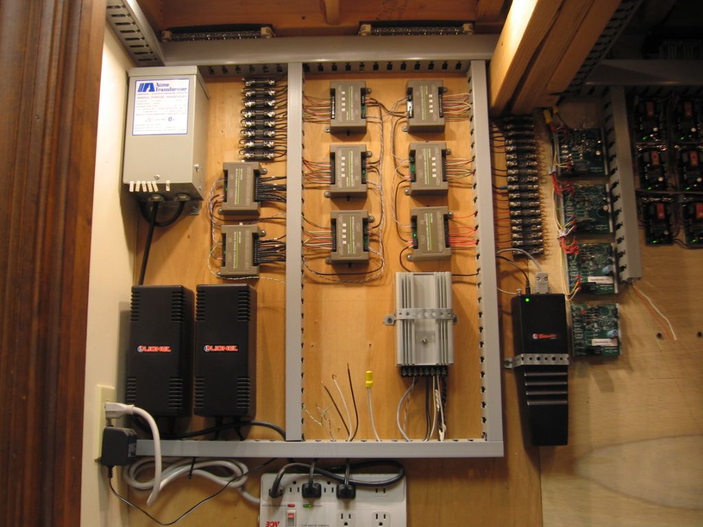
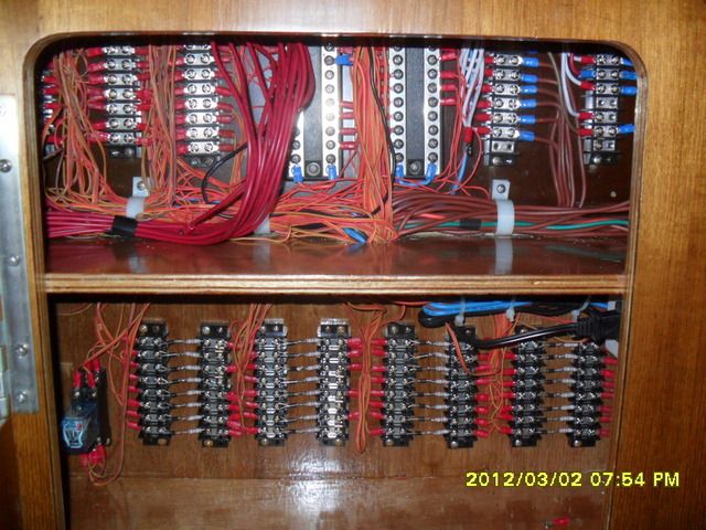
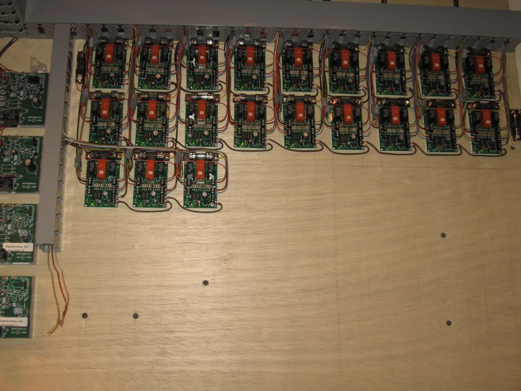
The pictures show a model railroad Patch Board specifically designed for use with two MTH model 50-1004 Accessory Interface Units and the MTH 50-1001 DCS system. This patch board provides for easy connections for up to 40 control circuits per board. The Patch Board features convenient screw terminal blocks which provide for a total of 120 individual wiring connections.


Note: The MTH model 50-1004 AIU provides 10 control relay outputs designed for activating turnouts and another 10 general purpose relay outputs. The AIU general purpose relays can be used for operating various accessories or for block control when routing trains. The terminal strips are colored coded and individually numbered for ease of use. All wiring (not shown) when completed ensures that wiring errors for connections to the layout are minimized.


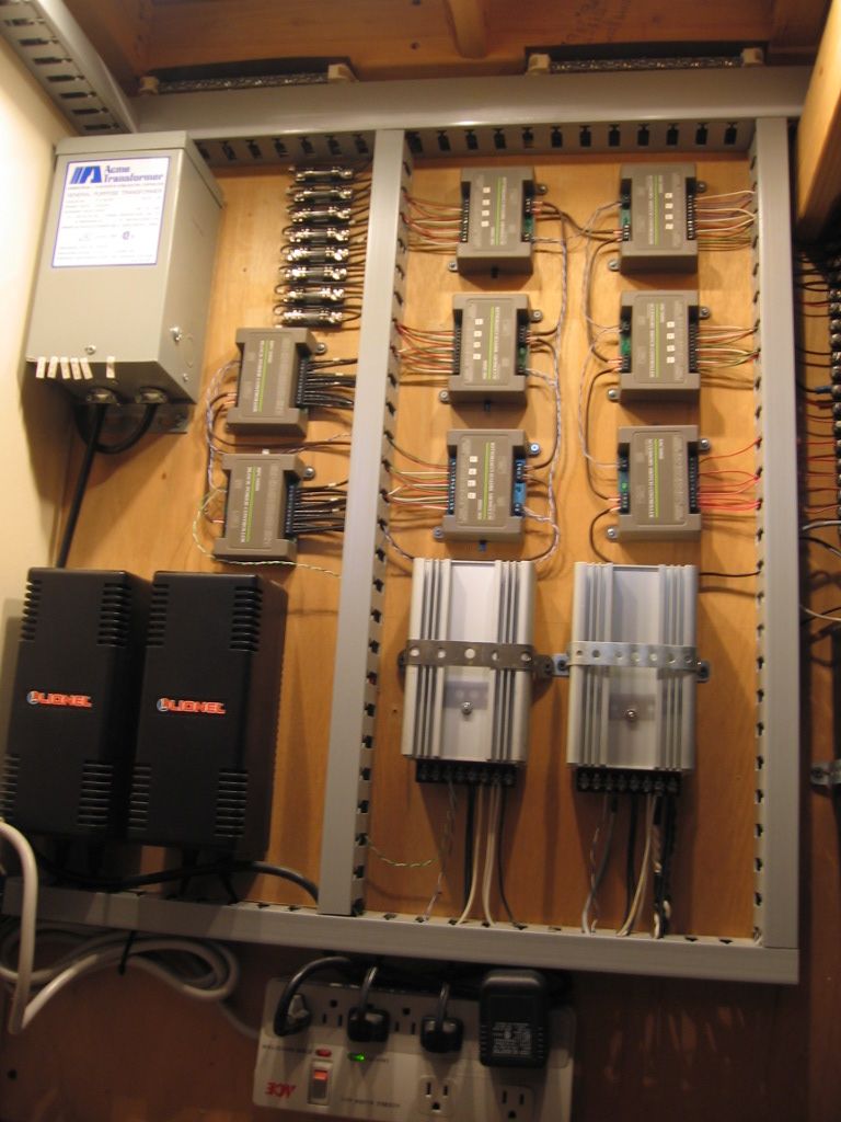
The model railroad patch board is completely portable and modular. The patch board is able to be easily connected to other modules which include:
1: Turnout control module that uses 12 volt relays to operate MTH turnouts (switches).
2: Block Control module that uses 12 volt relays to provide block signals to the various blocks on the layout.
3: Source Control module that connects to either the fixed or variable outputs from the MTH TIU.
4: Accessory Control module that connects to various operating accessories on the layout.
Note 1: All wiring is completely color coded and labelled by function.
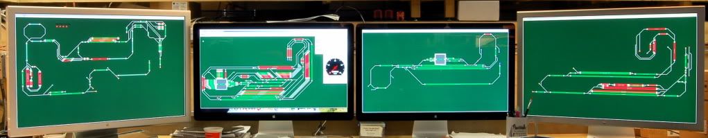
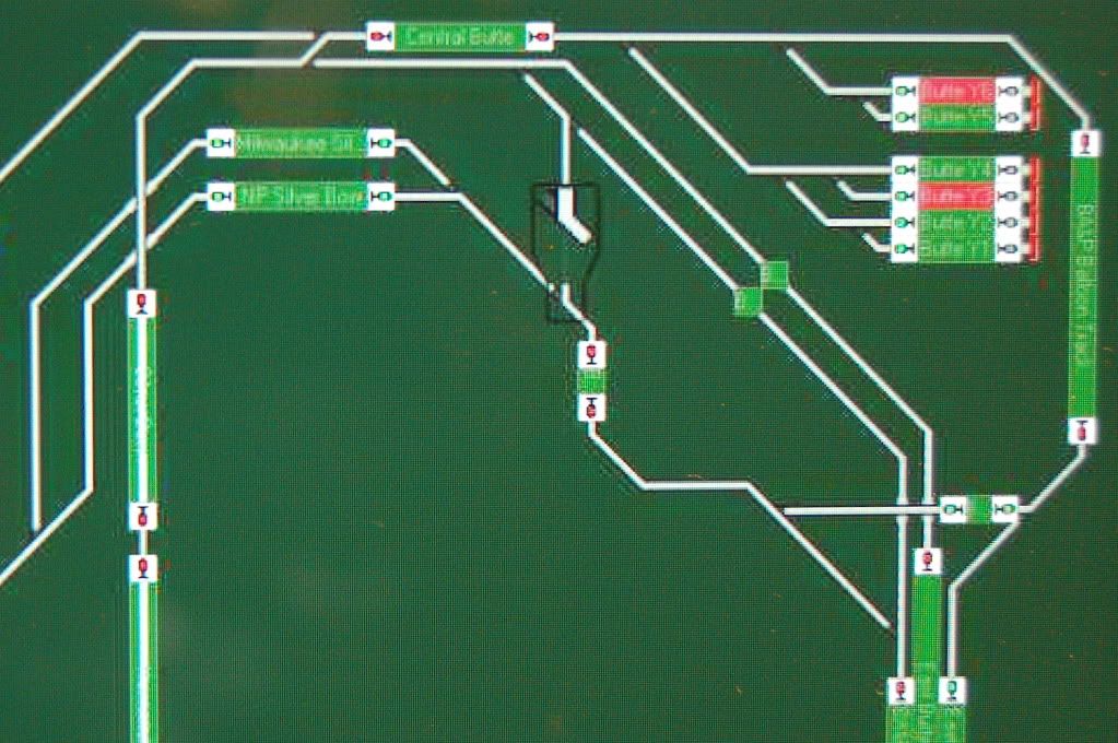
Note 2: A separate Dispatcher Center (not shown) displays the status of all turnouts and blocks. Various colored LEDs are mounted on a 1/16th scale representation of the layout plan.
Note 3: The Dispatcher Center only provides status. All control is provided by the MTH Hand Held remote controller system. (MTH 50-1001).
Note 4: All interconnections between modules are made using prefabricated wiring harnesses. This makes troubleshooting and upgrades very easy.
Note 5: All wiring is shown on individual CAD drawings made on a computer using Visio software and then paper print copies are place in a folder for reference.
Here is my control panel. The best advice i can give is ti sit down and paln out what you want and then make sure you plan for future expansion.


Does this count!!??????????
Or do I have to call the fire department? Greg ![]()
")
I apologize for posting this picture again, but considering the subject of the thread, I just couldn't resist it any longer.... ![]()

River-City 3 railers panel
Very impressive
John
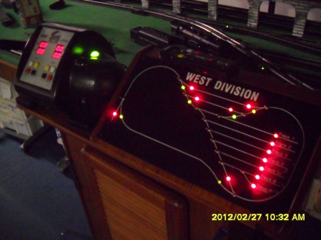
This was built by AGHR member Frank Davis to control the turnouts in the harbor. It uses bi-color LEDs to indicate routing. Here's a preliminary test before we set the other LEDs. This is one of the nice features of Tortoise machines -- they have an internal resistance of 600 ohms so you can hook LEDs in series with them.

Here it is in normal operation:


CNGW, back in the day I would have written you up for the excessive use of extension cords in lie of permeant wiring...hahahahah... mine is no better...
jz
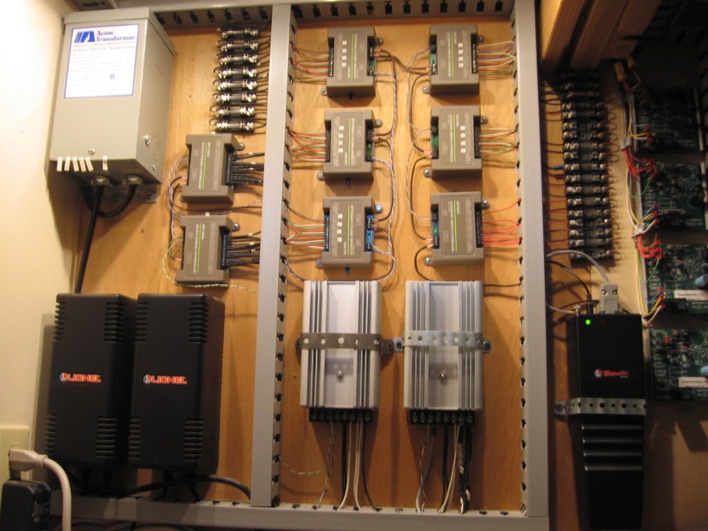
I have made a very simple Dispatch Center that shows the status of all turnouts and blocks. This Dispatch center is wired to an MTH 50-1004 AIU which is used to control the turnouts and the blocks. No hand switches are used. All turnouts and blocks are controlled by the MTH 50-1001 system using the hand held controller. The Dispatch Center has red, green and amber LEDS for indication.
I also have two separate control boxes that allow me to select turnouts or blocks manually.


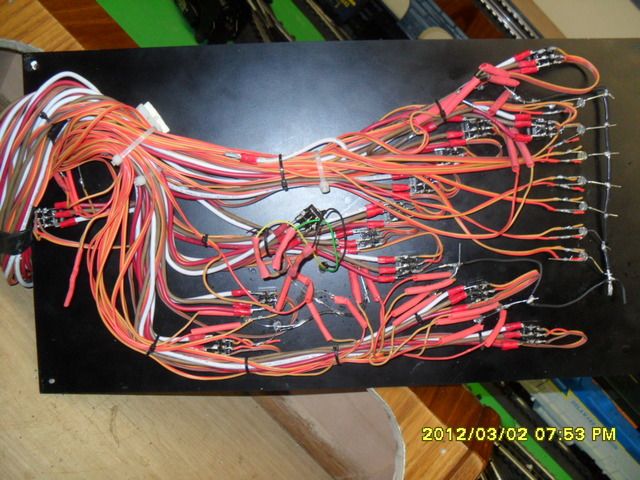
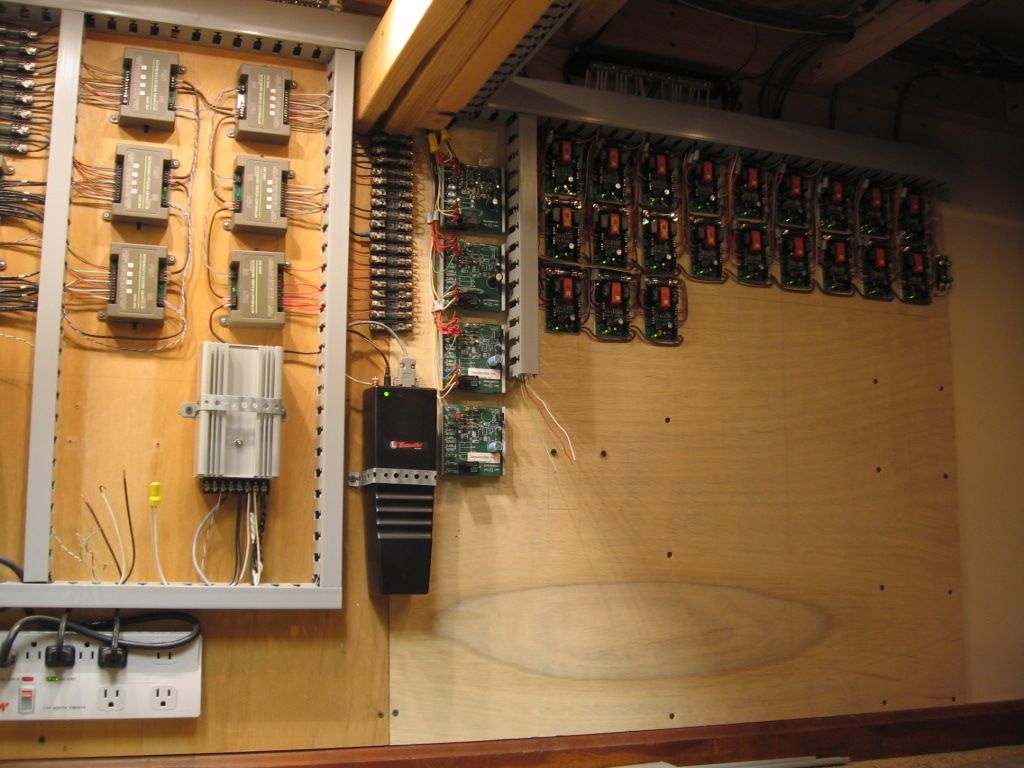
To simplify wiring I have built a relay interface board for controlling my layout via the MTH 50-1001 DCS control system. This board contains 20 high current relays which are used for controlling turnouts (switches) and block feeders. As a standalone interface this relay board could also be used with "manually" operated toggle switches if desired. However it exactly matches the color coded terminal blocks shown on the AIU Patch Panel.


Just curious, why do you need high current relays for switches?
The Relay Panel is used since I wire all the AIU Outputs using 12vdc circuits. This means that the IN terminal on all the AIU outputs is tied to 12v COM (common). The AIU relays carry only about 1/2 ampere maximum which is just enough to activate the relays.
I use the AIU internal relays to control track voltage "blocks" by activating separate external block relays. Therefore the external relays route the TIU track voltage to various location on my layout.
A second reason for using 12VDC at the AIU outputs is that I use this same signal to power the LEDs on my Dispatcher Board (annunciator panel). The Dispatcher Board includes LEDs for turnout "position" and "Block" status.
Note 1: I also have a dedicated 12v relay for selecting between "fixed" and "variable" TIU outputs.
Note 2: The MTH turnout solenoids are all powered by a separate 18vac power source. They do NOT use track power. All the 18vac turnout control circuits are current limited as well as protected by fuses and circuit breakers. Current is limited to 1.5 amperes by individual limiting resistors. If any fault (short circuit) occurs in any turnout the fault is "cleared" without affecting any other turnout or track functions.
Note 3: All wiring to the individual blocks are "home run" circuits that use 18AWG "shielded" stranded pairs. The wire is the same as used for alarm circuits in commercial installations.


The AIU relays are rated at 10 amps @250VAC. I don't see the need for booster relays on all the outputs.
I use the AIU internal relays to control track voltage "blocks" by activating separate external block relays. No TIU track voltage is routed through the AIU. Therfore 20 volt signals from the TIU remain outside the AIU. These external relays route the TIU track voltage to various locations on my layout.
The terminals on the AIU are very small. I cannot easily connect 18 AWG wire at these points. However my Relay Board uses large "Euro" style connectors which makes wiring very clean and neat.
Note: My "home" run wiring provides cabling that connects to both the center rail and one outside rail.
The AIU relays are rated at 10 amps @250VAC. I don't see the need for booster relays on all the outputs.
Actually, I believe the AIU relays are rated at 4 amps.
Doubter!! I opened up my AIU before I posted. The printing on the relay shell is UL/CSA 10A @ 250VAC. There is another symbol (European listing?) of 5A @ 250VAC. I would say that 10 amps at 20 volts AC is appropriate for our applications.
Son of a gun, I was told they were 4A relays! That's good to know. That came up in a discussion of using the AIU to control track power.
I wonder if the PCB traces will support the 10A capacity of the relays, perhaps that's the limiting factor?
Doubter!! I opened up my AIU before I posted. The printing on the relay shell is UL/CSA 10A @ 250VAC. There is another symbol (European listing?) of 5A @ 250VAC. I would say that 10 amps at 20 volts AC is appropriate for our applications.
Dale, I'm going to have to call you on this point. I don't see any 10A relays.


It's been about two decades since I worked there but:
http://www.johnmaggs.fsnet.co....nt/MIDAS%20XL200.jpg
I just can't remember the model number of the Midas control. It did say Supertramp on it! ![]()
I should have been this guy:
http://media.soundonsound.com/..._Live_Legends_05.jpg
Oh Ben...........
We have uncovered a significant difference! My relays are also Omron, but they are G5LE-14-ACD with the 10 amp rating for UL/CSA. Looks to be the same package, just a different rating! Mine's bigger than yours!!!! ![]() You know, size does matter!
You know, size does matter!
Joe, the audio faders in those consoles are my bread and butter. I am the North American distributor for Penny & Giles faders that are manufactured in Wales. Some of the consoles have over 100 input channels and faders! The big ones are for 3-man film dubbing applications, but there are some 96 fader consoles in recording studios.
I guess we need to be careful recommending more than 5A for AIU's. ![]()
I know someone told me the ratings were 4 amps.
Here it is, in Barry's book.
The AIU's relays are rated for no more than 4 amps. If more than 4 amps are passed through an AIU's relay the relay can be damaged. Therefore, the expected amp draw for any tracks controlled by an AIU relay must be less than 4 amps
I bought my (then broken) AIU from Barry. I have emailed him to see if maybe his was an early unit or if he knows the history of the change. I don't see any date codes on the assembly, but the ULN2803As have a W99xxx that could indicate 1999. The PC board is copyright 2000. Maybe an early prototype/pilot run item?
Sounds like an early one, I guess they thought twice about sending 10 amps through the PCB and terminals. ![]()
The AIU relays are rated at 10 amps @250VAC. I don't see the need for booster relays on all the outputs.
Those large high current plug-in relays are dirt cheap and easily replaceable from any auto parts store. Compared to sending the AIU back to MTh, waiting a "hundred years" for repair and return plus having part of layout disabled because missing AIU functionality. AND the fact you don't have to try and get those teeny weeny wires into those AIU connection blocks openings (which seem to get smaller each year). Rather have an auto relay fail from high current than burnt up traces and light duty relays.
But just my opinion, Your mileage may vary.
John, can you check the date codes on some of your chips?
Barry wasn't much help in solving the puzzle.
Dale, I'll pull it back apart later and see what I find. I actually have two of these, I might look in the other one as well, I know one is earlier than the other.
rrman\
Could those relays be used in a similar way to connect the large AWG wires into the Lionel/IC BPCs, etc?
Ralph
John, can you check the date codes on some of your chips?
Barry wasn't much help in solving the puzzle.
The photos didn't come out as good as I'd like, but I think I see some 2007 and 2008 chips in each of them. Specifically, the 74HC154 chips are of 2007 manufacture and the 74HC165 chips are of 2008 manufacture.
They're both also equipped with the 5A relays.
1st AIU


2nd AIU


Here's my small panel:

I incorporated the Z-stuff switch controllers in the panel.

Panel construction details:
http://bobs-train-blog.blogspo...0/control-panel.html
http://bobs-train-blog.blogspo...0/10/why-switch.html
Bob
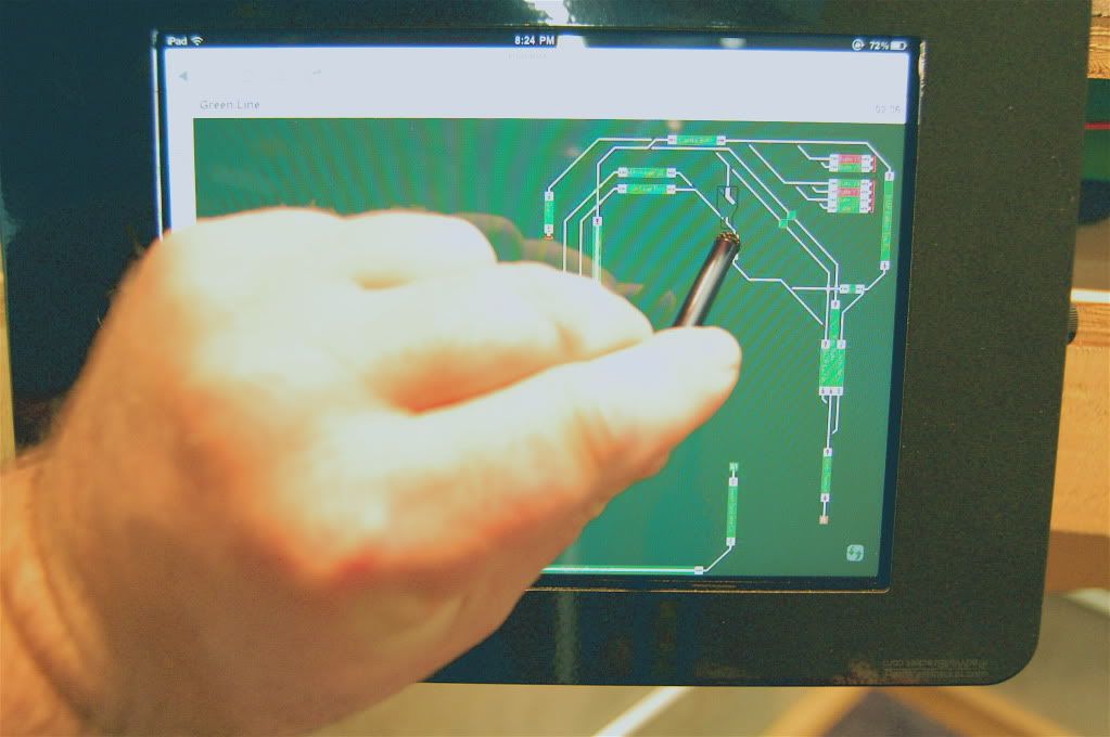
Here's mine - courtesy of JMRI, an Arduino, and a touchscreen monitor:

I have added a Power Monitor Board for use with my MTH DCS system. The Power Board has two identical circuit breaker boxes each having 20VAC voltmeters and pilot lamps. The circuit breakers are fast acting 5A resettable circuit breakers.
This board monitors two fixed TIU output channels.
Note 1: Power for turnouts (switches) and accessories is provide by separate power panels.
Note 2: Power for the TIU is supplied by a separate MTH Z750 brick.


What size resisters for the LED's?
For 12V, you'd probably use anything from a 470 ohm or larger. Unless you need blazing bright, I'd probably consider a 1K for the application.
I have built an Accessory Power Distribution Board for powering various operating accessories such as stations and towers, etc. I use 14vac for all accessories. The Power Board includes a 5 amp circuit breaker and 4 MTH 50-1014 Terminal Blocks. Each terminal block supports 12 circuits (positions). I have also added a specific lamp on the power box that will indicate if the circuit breaker has tripped.


I have built a specific power supply and distribution board for powering various operating accessories such as stations and signal towers. This board includes circuit breaker protection and 4 MTH 50-1014 Terminal Blocks for distribution to various accessories. Each block had 12 positions.


Joe, the audio faders in those consoles are my bread and butter. I am the North American distributor for Penny & Giles faders that are manufactured in Wales. Some of the consoles have over 100 input channels and faders! The big ones are for 3-man film dubbing applications, but there are some 96 fader consoles in recording studios.
Yes, I've heard of them. If I remember right they are the best.
I could have used some years ago when the crowd dumped beer into my mixer. Never worked as they should again.
I never worked on a board with more than about 48 (or 60??) channels. I really can't remember much of anything!
I'm always trying to use some old stuff to make the RR sound better. Guys can't understand why I want to. It's not the volume I'm after. It's the quality. If I were rich, I would have the basement set up as a whole train experience. Lights, sounds, smells and the whole deal!
On my control system I have extensive circuit breaker protection.
The outputs from my Lionel KWs all have a 5 ampere circuit breaker. See the attached photo which shows a power distribution board containing 2 circuit breakers and 2 voltmeters.
I also have circuit protection for the MTH TIUs. For all TIU outputs I also have 5 ampere circuit breakers.


Here's mine - courtesy of JMRI, an Arduino, and a touchscreen monitor:
How about tellings us a little more about your set up? Would it run from an iPad? Is your layout HO? Looks really cool.
Trainchief
Does anyone have new control panel photos? This thread seemed the most recent/active so please reply here.
There was another thread on this topic here https://ogrforum.com/t...panel-s-control-area
My control panels are only temporary, eventually everything will be controlled by computer with JMRI like Professor Chaos.
This one controls 20 switches in one section of the layout.
This one will control the hidden yard once I get it installed.
Here you go!

Pete
OK! NOW what is this unique piece?

Inquiring minds want to know!![]()
OK…Let start at the top…
This is the control room of the San Leandro Historical Railway Society's outdoor G&O Division. We have an outdoor O and G Scale garden RR. Our controls are housed in a tough shed and all wires run from the shed to the layout.
On the top shelf we have two Z4000 which power the O lines. The one on the left manages the inner loop which is deiced into two divisions, east and west; and then two additional blocks. The Z4000 on the right manages the outer loop's main line, which uses the start system and has 15 blocks and the yard, which is composed of four 7' through and through sidings. This line is controlled buy the Lionel TMCC and the TMCC control box is mounted on the wall. We started to set up for DCS and have the TIU mounted on the wall as well.
On the lower shelf is the Bridgeworkz power unit for the G Scale. it power two loops which each have award siding. We can see on e of the UR15s mounted on the wall just left of the TIU. we have tow of these and are not really lead with their reliability. We will are exploring a DCC system for our outer loop on the G line. Yo can also se the two control FOBs on each side of the Birdgeworkz unit. the small fan unit to the right on the lower shelf is our power unit for one of the water features we have.
All of the units are powered by three individual electrical power strips. Running outdoors is not for the timid or weak of heart. We have a great time with it and enjoy sharing the challenges, our learning experiences, and how we have made it work.
Who knows may be someday someone will visit us and decide to write about our project. Till then we just roll along.
Thanks for asking about our control board.
jeff
Here is what I am working on for the Hidden Pass Junction RR. The panel itself is complete other than I have to add (insert from behind) the LED's at each turnout. The panel is 18" x 36", and I am working on the wiring now.
I'll post more pictures later today or tomorrow under a separate thread. (I am just testing the new forum posting ![]() )
)
Alex
Yea, I know this post (the one I am specifically replying to) is almost 2 1/2 years old, but isn't that the beauty of this forum? One can gain valuable insight and knowledge from others, regardless of how long ago?
I've poured through the forum looking at different control panel designs and layouts, and honestly, all are very good. But the dilemma for me is, which one most closely matches what I've envisioned for my own design? This is certainly not to say that one is any better than another, but more accurately, a question of what other design has the characteristics I'd like to incorporate...not good or bad...just a personal choice.
The above board is what I'm looking to accomplish, and I already have the appropriate switches & multi-colored LED's (and mounts) to accomplish it. But, I have some questions:
1. What material was used? In my experience, Plexiglass cracks to easily, where Lexan doesn't, but is more susceptible to scratches. Any recommendations?
2. The line drawings for the track sections are exactly what I would like to accomplish, and like most people these days, I can print high-quality drawings on photo-quality paper. But this almost looks like some sort of self-adhesive 5mm tape was used (of various colors). I'm all for that, but a good understanding of what others have tried, succeeded, and failed with would be greatly appreciated.
3. I own a professional-grade label maker that allows me to produce labels with text of "black-on-white" or "black-on-clear" Mylar strips, of various thicknesses depending on the cartridge I choose. However, I'd rather not as a "Single-print" of the entire board would be better, but then again, my printer is limited to 8.5x11.
4. If necessary (based on forum member suggestions), I'm willing to go to a professional print-shop and have my layout, like above, printed on a single sheet.
5. Many panels were self-described as being a "sandwich" of two layers of some sort of clear plastic with a printed design between them. Because the thread length of the mini (not "micro") toggle switches is limited (8-10mm), if I choose to do the "sandwich" method, from experience, what thicknesses of material would I need?
All tips, advice, and contributions most welcome.
Here is what I am working on for the Hidden Pass Junction RR. The panel itself is complete other than I have to add (insert from behind) the LED's at each turnout. The panel is 18" x 36", and I am working on the wiring now.
I'll post more pictures later today or tomorrow under a separate thread. (I am just testing the new forum posting ![]() )
)
Alex
2. The line drawings for the track sections are exactly what I would like to accomplish, and like most people these days, I can print high-quality drawings on photo-quality paper. But this almost looks like some sort of self-adhesive 5mm tape was used (of various colors). I'm all for that, but a good understanding of what others have tried, succeeded, and failed with would be greatly appreciated.
...
the biggest problem i had with a laser printed panel cover was UV fading. blue lines seem to be the most susceptible and would disappear in less than a year.
Here is a slideshow of the progression of my control panel from its simple beginning in 2006 to its present finished form.
Here's mine - courtesy of JMRI, an Arduino, and a touchscreen monitor:
How are you using JMRI with O gauge trains? I'd love to do that myself but can't find a way for JMRI to talk to DCS.
JMRi does talk to TMCC, but Lionel's hardware to control switches are expensive and only control 4 switches per component. The DCS AIU controls 10 switches for close to the same price as the similar Lionel item.
JMRI with DCS would be great. Anyone know how to do that?
- RICH
So, here is an additional plea to Professor Chaos.
How do you use Arduino: Program for TMCC, program for LED lighting, program for switches or any other model railroading use such as coordination with control board?
I have an Arduino, but does not come with programing instructions and I also saw your post concerning control panel and Arduino.
WOW John, all you need is some of those 500. dollar chairs and it would look like NASA.![]()
Larry
HOLY CR*P John, does it land planes too?!!! That is WAY cool!!!!!!!!!!
Dan
Control Area
Click photo to enlarge.


Here is mine, worked on this with a friend who does alot of the cabinet work and wiring for the top, used RR Track to design the layout and print to size and laminated at Fedex print shop. various switch types for the accessories involved.


Access to this requires an OGR Forum Supporting Membership


")
")


")


")
")

")
")


