Just starting to fool around with arduino...

I want to adapt the arduino debounce example to detect trains.

https://www.arduino.cc/en/Tutorial/Debounce


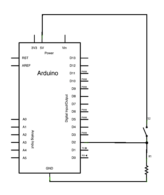
In my example the switch is actually a section of track with the outer rails insulated.

One outer rail is tied to transformer common ground, center rail is transformer hot. 

The other outer rail has a lead and two isolating pins on each end.

to make this work I am tying the outer outer rail lead to D2 on the arduino and the arduino +5v to the transformer common ground.

Anyone try this sort of thing?   Any advice or tips?


Original Post

Replies sorted oldest to newest

I'm using CMRI, so I'll be putting the DC ground on the outside common rail, since my inputs seek ground to be activated. If your inputs need voltage, then I think you have it right.

You might want to consider adding a couple components to each circuit. A diode to make sure AC doesn't get into your input, and a capacitor to smooth out wheel chatter in your signal. Sorry I can't tell you the values to use.

Last edited by Big_Boy_4005

I have love Arduino and have several projects in the pipeline related to model railroading. 

First off if you want to connect the arduino directly to the track you need a voltage divider to take track voltage to 5v, which will need to account for RMS unless you are running DC track voltage. I also think you will need to use the analog inputs since you will need the voltage divider. You are not reading a switch that the pin will read has high or low. I could be wrong. 

Note with anything there several ways to do things and arduino is no different. If I was going to do what you are trying to do. I would use some sensor for the Arduino, which maybe easier. What are you trying to do with the arduino? 

Joe - you are reccommending optical isolation on the inputs?

Chris - the arduino has its own dc power supply.  I am jus trying to use track common as a source for the 5v to activate the input.

Elliot - i think you are reccomendin a diode between thendetection rail and the arduino input? I am hoping the debounce logic in Arduino will smooth out chatter.

the purpose is a to control multiple train operation on a single loop.  The arduino ctrols a 16 relay board.

my loop  has 16 blocks.   It goes block1 tracks (about 100 inches) then one always on track, then one detector track (also the center rail on) then another always on track.  Repeat 15 more times.

The always on tracks ensure the trolley does not stop on the detector.

program is simple.   When detecting a train at detector N i deactivate block N to prevent a chasing trolley from catching up.   I then also reactivate block N -1 in case spme trolley was waiting for me to clear block N


Bill, you might do a couple of things. 

First off, I like to have a little spike protection, for an application like this, add a .1uf cap across the resistor should be sufficient in this case.

I do switch debounce in an ISR (Interrupt Service Routine) as a rule, it allows me to have that process run in the background and I don't have to continually do the debounce function in the mainline.  All the mainline code does is check to see if the switch state is on or off.

Big_Boy_4005 posted:

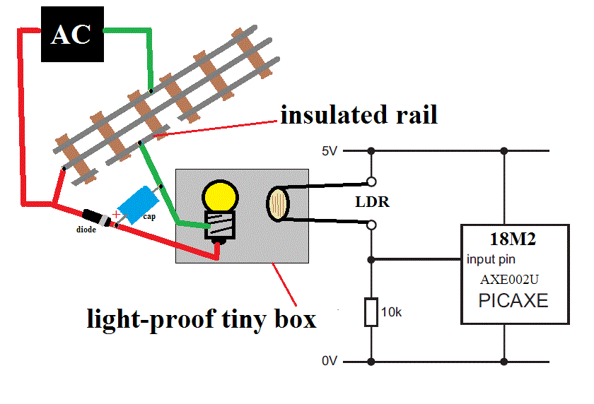
No Chris, I think his plan is to superimpose the 5V DC signal on the AC common. The train never sees the DC because the other side is only present at the Arduino. I've been using this principle for detection for over a quarter century.

I see that now. I didn't fully look at the diagram, sorry. It now makes since.

Chris

BillP posted:

Joe - you are reccommending optical isolation on the inputs? 

Hi Bill,

     Although it seems rather crude with the insulated rail and light bulb, it works very well with no risk of track power (and spikes) getting through to the computer or damaging an optocoupler chip.  The light can be inches away from the LDR. 

Take care, Joe.

The first thing is you absolutely want to electrically isolate the track from the Arduino.  Opto-couplers are cheap and will do this nicely.  I'd probably use active-low here, and use separate, isolated power supplies for the track side and the Arduino side.  

As for the de-bouncing, I think I'd go for a hardware solution here, placing a small capacitor and drain off resistor on the output side of the opto-coupler.  I'm not absolutely sure, but I think you would have a lot more room to fine tune the timing this way.  

If you want to do the de-bounce in code, I recommend using an interrupt timer.  I think you'll find plenty of suggestions on how to do this by searching for 'arduino timer interrupt' on google. There are several methods I've seen, but even the simplest, clunky, versions should work out just fine for your application.  

JGL

I use the attached circuit for isolated rail detection. An RC circuit debounces the track contact, and a Schmitt trigger generates a clean transition at the output.

I feed the track signal into an AC optocoupler - not so much to protect the circuitry, but because the Arduino is ultimately connected to the Legacy serial port. To avoid shorting the Legacy track signal, I needed to separate the Arduino ground (earth ground) from layout common.

You could probably do the debouncing in software; I did it in hardware because the circuit was originally designed for a Basic Stamp with very little memory or processing power.  If you wanted to do it in software, you should use some kind of integration rather than a pure sampling technique.

sensor

Attachments

Images (1)
  • sensor
Last edited by Professor Chaos
JohnGaltLine posted:

As for the de-bouncing, I think I'd go for a hardware solution here, placing a small capacitor and drain off resistor on the output side of the opto-coupler.  I'm not absolutely sure, but I think you would have a lot more room to fine tune the timing this way. 

The software solution gives you infinite fine tuning capability, so I'd have to dispute your comment about hardware being more configurable.   If you so desire in your software, you can even have individual debounce intervals for each input, hardware cost $0.

BillP posted:
... I am hoping the debounce logic in Arduino will smooth out chatter.

the purpose is a to control multiple train operation on a single loop.  The arduino ctrols a 16 relay board.

my loop  has 16 blocks.   It goes block1 tracks (about 100 inches) then one always on track, then one detector track (also the center rail on) then another always on track.  Repeat 15 more times.

The always on tracks ensure the trolley does not stop on the detector.

 Just so I understand the application, is it:

block detector control 16

BillP posted:
...

program is simple.   When detecting a train at detector N i deactivate block N to prevent a chasing trolley from catching up.   I then also reactivate block N -1 in case spme trolley was waiting for me to clear block N 

Ignoring the debouncing/de-chattering issue, IF one wanted to do this the old-fashioned way isn't this the classic method of cutting power to a trailing controlled block?  So each detector output simply drives the relay coil of the trailing block.

I'm curious about your plan to manage 16 detector inputs and 16 relay outputs.  Mux-demux shields or expansion boards to gain additional input and output channels can be spendy (more than the cost of an Arduino controller itself).   Given the low-cost of the controller boards, have you considered using multiple identical Arduino modules (running identical sketches) in lieu of messing with expansion hardware?


Attachments

Images (1)
  • block detector control 16
stan2004 posted:
I'm curious about your plan to manage 16 detector inputs and 16 relay outputs.  Mux-demux shields or expansion boards to gain additional input and output channels can be spendy (more than the cost of an Arduino controller itself).   Given the low-cost of the controller boards, have you considered using multiple identical Arduino modules (running identical sketches) in lieu of messing with expansion hardware?


Adding inputs usually isn't very costly - a 50-cent shift register gives you 8 inputs, and you can daisy-chain them.  The board below feeds 32 optically isolated input circuits into four serially connected shift registers. So I can read 32 track signals with three lines from the Arduino.

If you want to get really spendy, for about $1.25 you can get an I2C I/O expander like the MCP23017, which gives you 16 GPIO pins plus lots of programmable goodies like interrupts and pullups.

ACsensor board in place


Attachments

Images (1)
  • ACsensor board in place
Last edited by Professor Chaos

All,

Thanks for the input!  Some more information based on questions and comments above.

Stan,

Yes your diagram is correct.  Each section the relay controls is about 10 tracks long.  Then 1 track of always on, then one track of isolated outside rail for detection, then 1 more track of always on.

I am actually using Arduino Mega so 16 inputs and 16 outputs are not trouble.  The relay board has 16 inputs.

"So each detector output simply drives the relay coil of the trailing block."  That is the classic way.  In fact I had used that before with Gargraves track.  Because in the GG track all rails are isolated with the wooden ties, its easy!  Block N's outer rail activates a relay that kills N-1's center rail.  When Block N is clear the relay de-energizes and block N-1 center rail gets hot again.

By the way,  The one thing I learned from the first time doing the classic way is to leave a short always on segment between blocks.   Prevents stalls on the block transitions.

But ... In this particular application I used all old O-27 tracks!!! 

There are two helixes each made of O-27 ovals 4 curves, 1 straight, 4 curves, 1 straight.  The helixes rise for 5 and 1/2 turns, elevating 5 inches per turn.  This gives a grade of just under 5%.

I manually converted a bunch of straights to be isolated outer rail.  But the thought of converting over 100 pieces of 027 track was enough to make me mail order the arduino and relay board.

John,

Check out the clever way the arduino folks handle debounce without interrupts.  They simply record the time in millis() when the HIGH is detected in the loop() .   Then they check again to see if it has stayed HIGH for whatever bounce time.  I simply refactored there scalars to arrays for the 16 inputs and check each one in a for() loop in the main loop() function.

JGL and Chaos,

Thats three votes for optical isolators... Interesting.


Yes the original plan ties the +5v of the Arduino power to the Common AC ground of the train transformer.  Sharing a ground does not allow AC to flow to the arduino.  There is no potential / return to cause current flow.  I have used that same trick before.  DC powered relay sharing common ground with AC outer rail and activating the relay on isolated rail....


BillP posted:
John,

Check out the clever way the arduino folks handle debounce without interrupts.  They simply record the time in millis() when the HIGH is detected in the loop() .   Then they check again to see if it has stayed HIGH for whatever bounce time.  I simply refactored there scalars to arrays for the 16 inputs and check each one in a for() loop in the main loop() function.

Well, I don't know about "clever", it's just a shortcut to a more robust debounce routine.

Bill, you can debounce as many as you like using interrupts as well.  However, as long as the basic debounce works well enough for the application, that's all that counts. 

I keep going back to my aerospace roots when doing some of this stuff and trying to make it bulletproof.  We had to eliminate any noise on the inputs, even if it was repetitive, so having a routine that insured that the signal was solid for N time periods was one of the requirements.  Simply sampling after a set time period could yield a positive result because of bad luck.  Probably not as critical in a model train application.

BillP posted:
...

"So each detector output simply drives the relay coil of the trailing block."  That is the classic way.  In fact I had used that before with Gargraves track.  Because in the GG track all rails are isolated with the wooden ties, its easy!  Block N's outer rail activates a relay that kills N-1's center rail.  When Block N is clear the relay de-energizes and block N-1 center rail gets hot again.

...

I manually converted a bunch of straights to be isolated outer rail.  But the thought of converting over 100 pieces of 027 track was enough to make me mail order the arduino and relay board.

...


So to be clear, is the matter at hand how to do the de-bouncing of the detector sensors?  If you were successfully using the "classic" hardware-only relay method what exactly is different where an Arduino is required?  If this is really a get-to-know-you exercise to mess with the Arduino in preparation for bigger and better layout control then by all means carry on.  But if the Arduino is simply performing de-bouncing of the relay control signals to demote awkward stop-start stuttering of engines, then how about just a simple R-C filter on the input of your multi-channel relay module.

As Professor shows, a simple R-C filter feeding a Schmitt-trigger logic gate gives clean transitions.  This could drive a relay (no Arduino required).  So the function of sampling the input multiple times to confirm it is stable high or low level for some period of time is done as a team effort by the R-C filter and the hysteresis of the logic gate.

schmitt trigger logic gate

But if your SPDT relay modules are those $1/channel eBay wonders, the hysteresis comes for "free" on each relay due to how a relay picks up at some voltage but does not release until a somewhat lower voltage.  So just add an R-C filter.  Since you already have the relay module, I'd think you can try this pretty quickly.  I demonstrated (with video) this isolated-outer-rail detector de-bouncing of relay control in this thread.  The R and C components would be, say, 10 or 15 cents per channel.

hardware debounce of relay module


Attachments

Images (2)
  • schmitt trigger logic gate
  • hardware debounce of relay module
Last edited by stan2004

To add to Stan's R/C filter, he help with my Arduino project and i tested just soldering the componets together in a clump and it works flawlessly. Since it was going to be on a club layout and I won't always be there to troubleshoot and talk about the process to drive the signals i figured i would produce a PCB. Here it is in picture forum. Still awaiting arrival of the actual board.

Screen Shot 2016-11-28 at 6.38.52 PM 

Attachments

Images (1)
  • Screen Shot 2016-11-28 at 6.38.52 PM

Stan,

I think you missed part of the reply before:

"But ... In this particular application I used all old O-27 tracks!!! 

There are two helixes each made of O-27 ovals 4 curves, 1 straight, 4 curves, 1 straight.  The helixes rise for 5 and 1/2 turns, elevating 5 inches per turn.  This gives a grade of just under 5%.

I manually converted a bunch of straights to be isolated outer rail.  But the thought of converting over 100 pieces of 027 track was enough to make me mail order the arduino and relay board."

The O27 tracks were free and fit the tighter size that I needed.  You see the helixes are mounted inside the bottom center of two mountains.


And the main point of the post was to see how folks interfaced Arduinos to layouts for block presence detection.


John,

You got me curious as you were touting the glories of interrupts :-)

I found this reference table about which digital pins can drive interrupts.  Looks like the Mega has only 6 interrupt enabled pins:

BoardDigital Pins Usable For Interrupts
Uno, Nano, Mini, other 328-based2, 3
Mega, Mega2560, MegaADK2, 3, 18, 19, 20, 21
Micro, Leonardo, other 32u4-based0, 1, 2, 3, 7
Zeroall digital pins, except 4
MKR1000 Rev.10, 1, 4, 5, 6, 7, 8, 9, A1, A2
Dueall digital pins
101all digital pins

An interrupt-driven debounce routine doesn't need to (and probably shouldn't) use an interrupt driven by a change in pin state.

If you don't need to count the number of times the switch is closed,  your program would look something like this.  Assume you want to turn the relay off if the switch has been open for 100 milliseconds:

Main loop:

  • If switch[x] closed:
    • Turn on relay[x]
    • Set BounceCounter[x] to 100
  • If BounceCounter[x] == 0
    • Turn off relay[x]


Interrupt routine, set to fire every 1 millisecond:

  • For all BounceCounters, if BounceCounter > 0, decrement BounceCounter by 1


As you mentioned,  you can achieve the same result by storing the time the switch was activated, and checking it against the current time in the main loop. But the interrupt approach is simpler to program and maintain.

Last edited by Professor Chaos

Add Reply

Post

OGR Publishing, Inc., 1310 Eastside Centre Ct, Ste 6, Mountain Home, AR 72653
800-980-OGRR (6477)
www.ogaugerr.com

×
×
×
×
Link copied to your clipboard.
×
×