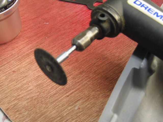
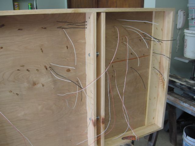
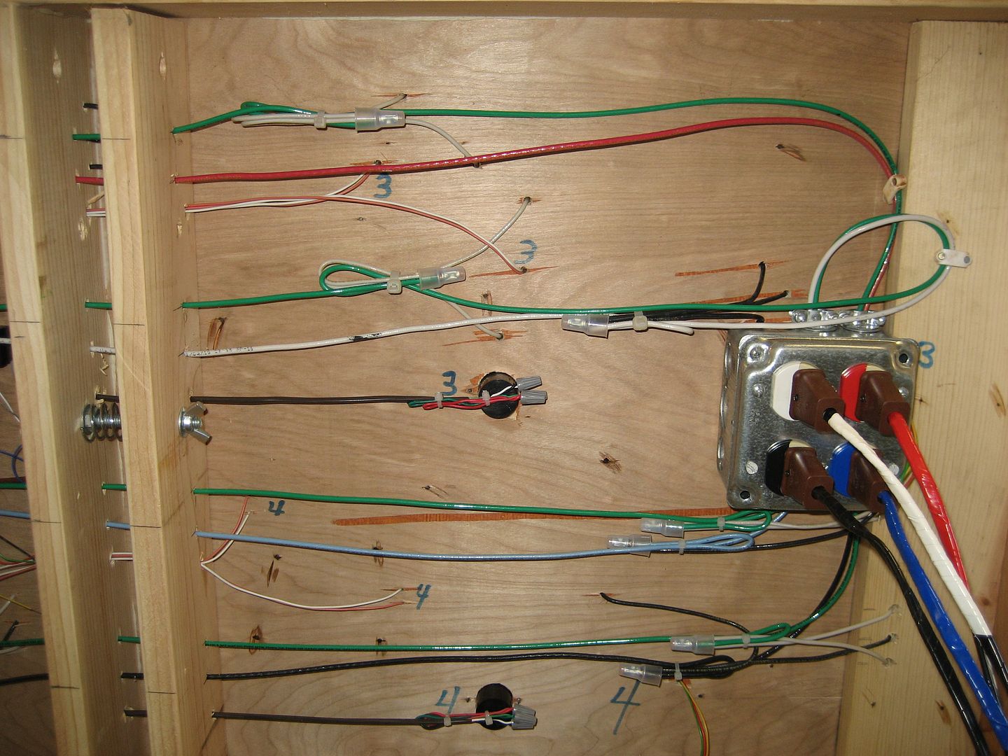
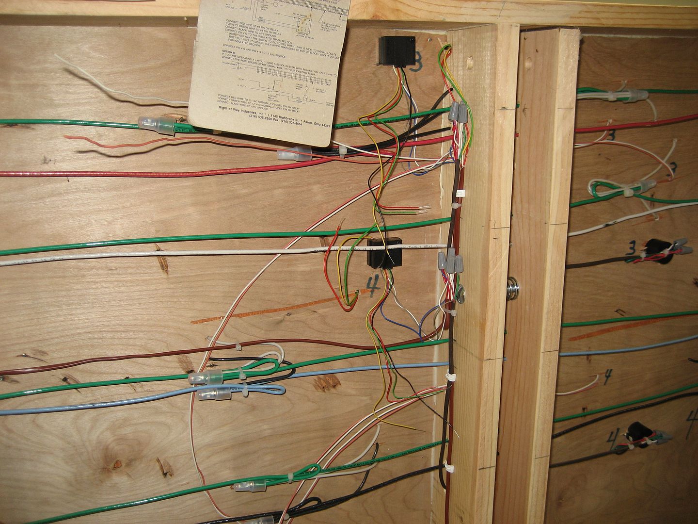
Hi all, I started a new layout with help from members here (DoubleDaz) Dave, Carl on the layout ideas and started using Atlas 3 rail track and wondering about the track connections.  Some of the track connections have a small gap in the connection  I used new rail joiners since I had to cut track for the layout.  Is that going to be a problem for connectivity between the tracks or will the rail joiners make it ok for a small gap between tracks.  Would I need to solder each connection for good connectivity? ( a big job) I purchased a 6" cut off saw from Harbor Freight so the cuts are clean but some have small gaps. I notice the rails are a bit flimsy and snap off easily when pushing track together. 

Another question I have is about  my DCS and using feeders wires ( yes I have the download book, but looking for other idea methods)  are they really necessary for my horse shoe type layout that is 16 x 16 x 10 with some areas 2 foot wide down one 16 foot area.  Would there be a signal problems with this size ?  and if feeders are required, what is the best and easy way to run them.  I do have an MTH Z-4000, an old 275 zw lionel,  old 125 w, and (2) 80w Lionel transformers, so power is their.  Thanks for the help 

Original Post

Replies sorted oldest to newest

Not seasoned yet posted:

Hi all, I started a new layout with help from members here (DoubleDaz) Dave, Carl on the layout ideas and started using Atlas 3 rail track and wondering about the track connections.  Some of the track connections have a small gap in the connection  I used new rail joiners since I had to cut track for the layout.  Is that going to be a problem for connectivity between the tracks or will the rail joiners make it ok for a small gap between tracks.  Would I need to solder each connection for good connectivity? ( a big job) I purchased a 6" cut off saw from Harbor Freight so the cuts are clean but some have small gaps.I notice the rails are a bit flimsy and snap off easily when pushing track together. 

Another question I have is about  my DCS and using feeders wires ( yes I have the download book, but looking for other idea methods)  are they really necessary for my horse shoe type layout that is 16 x 16 x 10 with some areas 2 foot wide down one 16 foot area.  Would there be a signal problems with this size ?  and if feeders are required, what is the best and easy way to run them.  I do have an MTH Z-4000, an old 275 zw lionel,  old 125 w, and (2) 80w Lionel transformers, so power is their.  Thanks for the help 

Highlighted above..did you mean the plastic snaps ..yes they can break but the joiners will keep things lined up. I use the atlas joiners and no solder and bolt the track sections down with the Atlas screws. I violate DCS protocol  an have single feeds to (2) 26x9 foot loops. My DCS has been very stable.I run mostly big MU's.

Last edited by willygee

What is the size of the small gap? You should be ok with a small gap here and there. I have a couple of them at a couple of connections of track to switches. Mine are probably no larger than 1/8 inch or so and I have had no problems. I didn't solder any of my track joints, Atlas track joiners only. Also, I have not experienced the 'flimsy rails' as you describe? The only rail I have ever knocked loose was on a piece of track I dropped on the concrete floor.

Yes, you will need isolation joints in the center rails every 10-12 sections (joints) of track. Then yo need to run from your power source to a terminal block and then to each block of track, preferably connection the power near the center of each block. Just like Barry's book describes. If you do that you will have a nicely working layout and your DCS system will work with very few problems if any. Better to do it correctly than have problems and have to re-do it later out of frustration.

Several years ago when I got back in the hobby, I had a 3-1/2' by about 7' loop of track with one power feed and no block isolation joints. I had DCS problems with Engine not found, not on track, and other errors etc. quite often. I did not think anything that small would matter as far as wiring, DCS etc. Then I wired my current and more permanent layout as described in Barry's book and have had no DCS errors at all in over 4 years now. That is, other than me forgetting to power a siding before trying to start the engine that is parked on it. That has sure made a believer out of me in the track blocks and feeding them with MTH terminal strips and following Barry's book! 

Last edited by rtr12

Thanks for the info,  The gaps are not very big but I was not sure if it was  not a tight connection it would cause problems to trains not getting power over those rails.  I had some track rails come off the plastic ties seems like the rails snap back on but some of the little dimple tabs break easy and the rail is loose at the joints.  I guess I could glue the rail down.  I had trouble snapping some of the tracks together with the rail joiners and when pushing them together the rail come undone from the tabs.  I have the mth blocks so I guess I will run the feeders   Thanks,

Not seasoned yet posted:

Thanks for the info,  The gaps are not very big but I was not sure if it was  not a tight connection it would cause problems to trains not getting power over those rails.  I had some track rails come off the plastic ties seems like the rails snap back on but some of the little dimple tabs break easy and the rail is loose at the joints.  I guess I could glue the rail down.  I had trouble snapping some of the tracks together with the rail joiners and when pushing them together the rail come undone from the tabs.  I have the mth blocks so I guess I will run the feeders   Thanks,

I would suggest running wood ties, stained or painted black, of appropriate size under the bare rail. Much more stable long term. You'll find appropriate strips at your hobby shop or hobby lobby. If you plan on ballasting you'll never notice the wood ties.

I got one used switch from ebay that had about a 1"-2" piece of rail that was detached when I got it. Still have it, but never fixed it. Glue was going to be my fix, if I ever get around to it. Personally, I have not had any rails come loose from any of my other track whether new or used so I don't quite know what is going on with yours there? 

From GRJ's post above, I guess my gaps are small enough to not have any effect on my traction tires. At least no problems with them so far. If you do have a larger gap you can sometimes 'gently adjust' the rail with gap a little to sort of split the difference and make smaller gaps. I had to 'adjust' the rails a little on a couple pieces of my track so they fit snugly, they were a tad too far to one end when new.

Definitely use the isolated center rail blocks and your terminal strips and good wire, #14 or #16. You will be very glad you did and thank yourself later on!

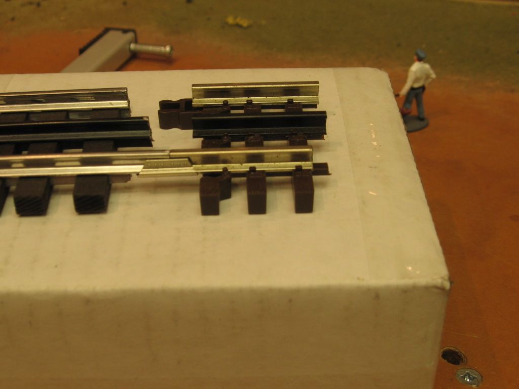
Atlas track does require a little more care, and you have experienced the usual problems.  If a rail separates from the ties, I drill small holes for HO spikes, put a dab of ACC (super glue) on the hole and insert the spike.  I don't replace every broken plastic "spike" but just enough to make the rail secure.

As much as I try to keep rail gaps tight, inevitably I will have some that are 1/8" or greater.  I cut off a thin segment of rail from a scrap piece with a Dremel cutoff disc and slide it into the rail joiner to fill the gap before connecting the rails together.  Another reason to avoid gaps is to cut down on rail/wheel noise, although some folks want as much clickety-clack as possible.

Here is a thread on repairing Atlas track.

Bob

Not seasoned yet posted:

Another question I have is about  my DCS and using feeders wires ( yes I have the download book, but looking for other idea methods)  are they really necessary for my horse shoe type layout that is 16 x 16 x 10 with some areas 2 foot wide down one 16 foot area.  Would there be a signal problems with this size ?  and if feeders are required, what is the best and easy way to run them.  I do have an MTH Z-4000, an old 275 zw lionel,  old 125 w, and (2) 80w Lionel transformers, so power is their.  Thanks for the help 

While i'm sure the experts will jump in to "correctly" advise you, I would wire it as you want.  I say this because of all the experience I've had with DCS wiring:

My first layout was 8 x 16 and comprised of 2 loops of track.  Each loop had only one power drop to provide power to that entire loop - 18 AWG stranded wire power drop, connected to my Z4K.  Perfect "10" signal and constant voltage throughout.  

My second layout was 33 x 16 and comprised 4 loops of track.  I wired each loop obsessively in accordance with the MTH protocol.  I used OGR 14 AWG stranded wire for my power drops, centrally located each power drop in each track block, and power drops in a given loop ran to an MTH terminal block for the given loop that was powered by its own Lionel 180 brick.  Perfect "10" signal and constant voltage throughout.

In both cases, everything from conventional to all my Legacy and Atlas TMCC locomotives ran perfectly.  Every one of my MTH locomotives, however, would regularly have glitchy performance.  They would slow down and then surge, turn themselves off.  Sit there "on" and not respond to commands, etc.  Or run and not respond to commands.  And the remote had regular nonsensical error messages (engine not on track - when the engine was already running around the layout and responding just fine, etc.).   

Finally, if you (a) want to include turnouts in your layout; and (b) want to power each of the three legs, and (c) don't want to pull out the embedded turnout wiring to create three isolated legs, then you cannot, by definition, wire strictly via DCS protocol.  

So again, wire it as you like - you'll have the same ups and downs and amount of joy running your trains.  

Last edited by PJB

I would respectfully have to disagree here. In over 4 years now, I have had no ups and downs, glitchy performance or any other problems with MTH locomotives since wiring my layout per DCS recommendations from Barry's book. I also have a few switches and no problems there either. All Atlas track & switches. I realize layout vary due to many things, but I really have had no problems other than starting an engine and forgetting to power it's siding first.

The wiring suggested in Barry's book made a believer out of me. I had problems previously with a couple of very small temporary layouts (3-1/2' x 7' approx) that also had all 10s for signal. Back then I didn't think the wiring mattered either, especially not on something that small. 

RTR - that's a great data point.  DCS functioned perfectly on both my layouts too ... at times.  Glad you posted this as again, I'm no expert and posts like yours help shape my knowledge as I learn more about this great hobby.  But if you've been on this or any other forum for a while (and I know you have) then you are aware that there are many people that also experience DCS problems like those I've experienced, regardless of how they've wired.

Given the OP's question was about DCS only, I wanted to share my own (star pattern and bus) experiences.  Yes, folks will say they've star pattern wired and have had zero DCS problems.  But there are just as many folks (if not more) that will tell you they use bus wiring and also have had no DCS issues (e.g. EricsTrains and I believe Marty Fitz, and many clubs).  And vice versa.  So, my point was, from a very pragmatic standpoint, given bus wiring is faster and less expensive, and may or may not make a difference in someone's actual operating experience, I think it's worth considering.  One opinion .... 

Last edited by PJB

Thanks for the imputs, but a question that I have also is if there is much difference in how you wire, example being running a bus wire through out and attaching feeders off of it OR running the wires to a the mth terminal block and then off the terminal to each section no matter how far the section is to it ?.  Also does the stranded wire make much of a difference compared to solid wire, is it better for the signal.  Is it best to attach the feeders to center rail at the middle of the block and is using the atlas terminal joiners the best way of doing it? I saw the  post of drilling into the rail and screwing the wire in and not soldering it  Comments ?  Thanks

Stranded verses solid wire - at the frequencies you are dealing with it probably does not matter though stranded wire carries more current per given voltage than solid wire and I believe has better signal carrying capability. I would stick with stranded for two reasons: (personal opinion tick with stranded)

1 - it is more flexible so easier to deal with when routing.

2 - I find it easier to solder or crimp with

Using a bus wire or MTH terminals is really six of one, half dozen of the other. Either technique works. The important fact to remember is because you are dealing with DSC is that each power / ground pair you run to track must be pretty much the same length. So if you use a bus system use it for both power and ground. If you use terminal boxes run power and ground to it then power and ground to the track.

Using the rail joiner for power / ground connection is fine. Soldering the wires directly to the track is better. Using a mechanical connection like I do with Splitjaw connectors is good also. Whether you wire to the middle of a block or the beginning or end really does not matter. It is distance between connections that matter. As to how far between power / ground connections depends on who you talk to. Opinions range from every 4-6 feet down to every individual track connection. Only caveat to this that probably everyone agrees with is the for turnouts make sure you have power / ground connection on each leg. If you are dealing with isolated or insulated track for accessories make sure you have power / ground on both sides.

If this is going to be a long term layout that you are going to scenic and run a lot, error on the side of caution. Put in more track power / ground connections then you think necessary. This ensures trouble free running of trains w/o having to rip up scenery to add need connections.

Joe

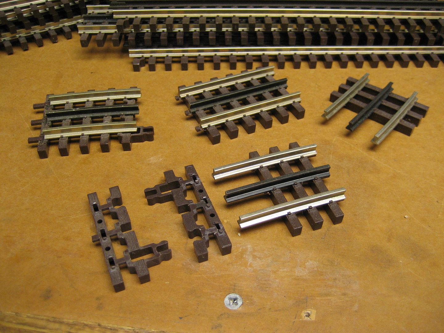
You can fabricate custom Atlas pieces using the 6057 tie end adapter.

History of the Atlas rail joiners, from a foggy head, accounts for maybe three different joiners.  First joiners were poor with little tension and corresponding poor conductivity.  A dimple in the bottom was added, which improved the connection.  Recent rail joiners are difficult to use, because of the high spring tension, and tight fit.  Conductivity much increased, but snap-together installation can be a problem.  IMO, Mike CT.     Patience required.  

You can use the rail joiners with Gargraves track. Gargraves left, the bottom profile has been removed with a dremel.

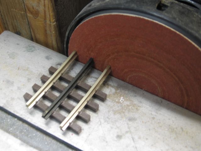
You can cut Atlas track with a fine tooth hacksaw blade.  I use a bench grinder to adjust final ends  of the Atlas piece. 

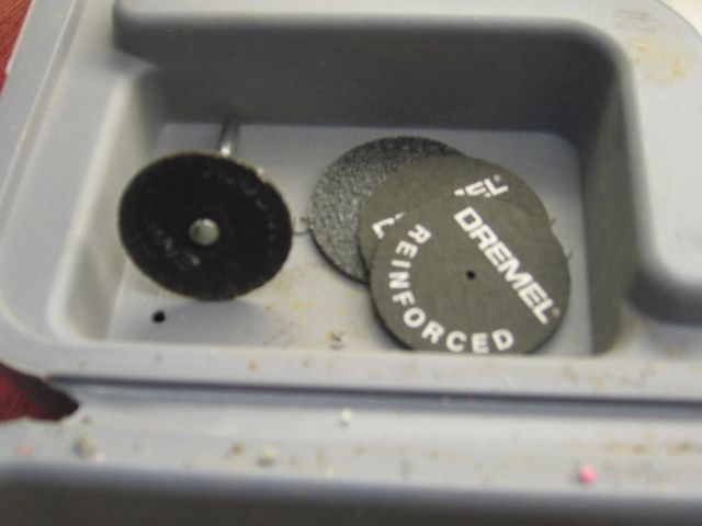
Cutting tool. 

Dremel right angle attachment and mandrel pictured. 


Last edited by Mike CT

PJB, Yes I know some layouts seem to work while others have problems. I have no explanation for the differences. My layout is the only one I have real experience with (and the couple of small temp layouts I had prior), there are no clubs or others I know with layouts to compare with. As it was pointed out to me here on the forum (by RJR I think it was), the outside rail is basically a 'bus' anyway, no matter if you follow the rules or not, as it is all connected with no blocks. Mine is the same way. So I guess it appears that the center rail is the one that really matters. Maybe someone else will have an a better explanation?

All I would do if building a new layout is try to follow the recommended guidelines as best as I could. Then if there are problems, I'd go from there, but at least I tried anyway. I was lucky I guess as everything here works great, but my layout is only 6' x 16', 2 loops and 2 TIU channels, isolated from each other. Size may matter here too? Lots of folks recommend connection the outer rails together as well, probably a real good idea too. But, I left one outside rail by itself for signals, accessory stuff, etc. and so far so good there.

Last edited by rtr12
Not seasoned yet posted:

Thanks for the imputs, but a question that I have also is if there is much difference in how you wire, example being running a bus wire through out and attaching feeders off of it OR running the wires to a the mth terminal block and then off the terminal to each section no matter how far the section is to it ?.  Also does the stranded wire make much of a difference compared to solid wire, is it better for the signal.  Is it best to attach the feeders to center rail at the middle of the block and is using the atlas terminal joiners the best way of doing it? I saw the  post of drilling into the rail and screwing the wire in and not soldering it  Comments ?  Thanks

I would try to centralize the MTH terminal block to make the drops shorter. You could use larger wire to the terminal block. Layout size makes a difference here too. How far are you talking about? A smaller layout may not make much difference, a large one could make a big difference in where you place things.

I like stranded wire for the reasons mentioned above, easier to work with and more flexible. Forum member Gilly (can't remember his forum name?) posted this wire available from Monoprice, #14 & #16 wire similar to the wire OGR used to have. OGR wire is what I used, if I get to my expansion I will use the Monoprice wire. This is good wire and easy to work with. At least it was for me.

I used the drill and screw  method for my layout: Ingeniero No 1's method of fastening the wire to the Atlas track. This is from another forum member, but there is a link to Ingeniero's original thread in the post. This post has pictures and a list of the materials used to make the connections and a link to the screw supplier. I have been quite pleased with the results here and it's pretty easy to do. Also, it's easy to move things around later if the need arises. 

Model Structures posted:

Stranded verses solid wire - at the frequencies you are dealing with it probably does not matter though stranded wire carries more current per given voltage than solid wire and I believe has better signal carrying capability. I would stick with stranded for two reasons: (personal opinion tick with stranded)

While I agree with stranded wire for easy of use, it doesn't really carry more current than a similarly rated solid conductor.  The reason some people think that it does is the skin effect.   However skin effect at 60hz is not an issue with any wire we'd ever use, it's 8420μm deep, that's 0.33" at 60hz!  Also, in order for stranded wire to provide measurable effects for skin effect at any frequency, the individual strands have to be insulated.  Wire with individual insulated strands is called Litz wire, I'm pretty sure you aren't wiring your layout with that.

gunrunnerjohn posted:
Model Structures posted:

Stranded verses solid wire - at the frequencies you are dealing with it probably does not matter though stranded wire carries more current per given voltage than solid wire and I believe has better signal carrying capability. I would stick with stranded for two reasons: (personal opinion tick with stranded)

While I agree with stranded wire for easy of use, it doesn't really carry more current than a similarly rated solid conductor.  The reason some people think that it does is the skin effect.   However skin effect at 60hz is not an issue with any wire we'd ever use, it's 8420μm deep, that's 0.33" at 60hz!  Also, in order for stranded wire to provide measurable effects for skin effect at any frequency, the individual strands have to be insulated.  Wire with individual insulated strands is called Litz wire, I'm pretty sure you aren't wiring your layout with that.

Yeah, but Mike Reagan - in one of the Lionel "how to" videos on Youtube said to use stranded because electricity travels on the outside of the wires.  You might be right GRJ, but I'm still going with what MR said, because he's MR.   

Well, in this case, Mike is wrong, but you're free to believe what you like.  Truthfully, Mike is technically correct, but just not for the wire we'll ever use. 

While it's true that for a given wire size and AC transmission frequency, skin effect comes into play, it won't with any wire we're likely  to be using.  FWIW, high tension transmission lines are large enough in diameter to actually take that into effect at 60hz.

So to consider these options with my layout which I mentioned before is a horse shoe 16 x 10 x 16 I would need to use multiple MTH  terminal blocks to space out the track wire, and connect power and ground to center rail or power to center rail and ground to outer rail ?  I have 9 switches most are on the siding where I will park trains and use uncouplers.  I included some photos of my layout under construction and still waiting on some tracks to come in.  Showing the 6" cut off saw I used to cut track which works nicely.

Attachments

Images (3)
  • 20181027_155121
  • 20181015_145324
  • 20181027_155132
Last edited by Not seasoned yet

NOT SEASONED YET, I looked at that 6" friction cut-off saw at Harbor Freight and was tempted to purchase it, but I wondered if it makes it through a piece of Atlas track in one swipe or do you have to flip it to complete the cut? Also, is the cut square or do you still have to disc sand the ends of the rails to even them up? I have a Milwaukee 12" but the friction wheels are much thicker and have more of a wobble, so they make a much larger saw kerf which I don't like. 

Solid wire has worked for me, each person has a preference.   Electrical construction wire up to #8 tends to be solid. Larger sizes stranded.   Using 14 ga solid easily solders to the sides or bottom of Gargraves track. 

Solid wire drops to be connected to track and accessory feeders, Fort Pitt Highrailer module. 


Add Reply

Post
×
×
×
×
Link copied to your clipboard.
×
×