What O Gauge parts, meters, tools will I need ?
What O Gauge parts, meters, tools will I need ?
Replies sorted oldest to newest
Great idea. What is a "USC track"?
quote:Originally posted by Locopops:
Joe,
Great idea. What is a "USC track"?
Univ. Southern California athletes who run, jump, etc.
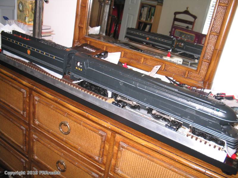
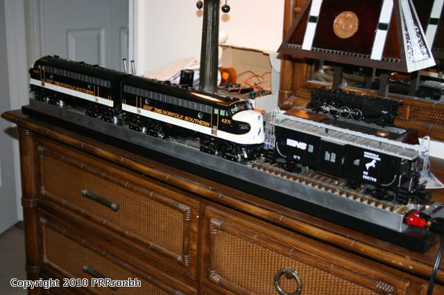
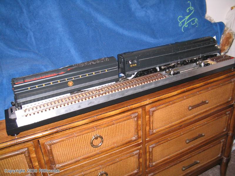
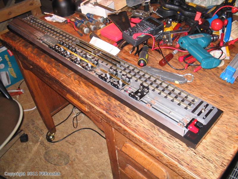
If I read your test setup correctly, you have two sections of track with a uncoupler track between them, and the track in front of the uncoupler track has movable rollers so you can line them up with the drive wheels on the engine so you can run the engine without it going anywhere.
Super trick. Where did you get the roller setup devices ?
That's a great idea.
Paul
The rollers were by "JAK Rollers" in NJ. But they were made to my specifications needed to fit my design.
Corvettte

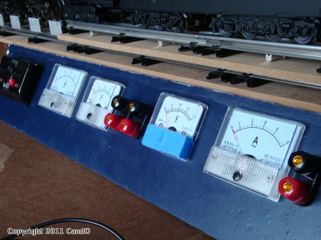
First off, I had a set of JAK rollers. I incorporated everything I thought I needed. I wanted to use banana jacks for the alligator clip leads. I purchased, on ebay, the banana jack binding posts and some of these banana plug to alligator clip. I also purchased these test leads. They are great for grabbing the wheel set and pick-up rollers for testing a loco when in an engine cradle. The panel meters were purchased on ebay. I bought them in 25 Volt AC and 5 amp.
The meters on the left are wired to track power, as are the left two sets of posts. The right top piece of track slides/glides on the lower track to fit any locomotive I own by placing the JAK rollers under the drive wheels. That upper piece of track can also be removed.
The meters and posts on the right are wired to the transformers fixed voltage. These are for test operating accessories, lights, and such.
If I want to test an operating car, I remove the JAK rollers and put a UCS track in between the upper tracks. When the UCS is not in use, it is attached to the back with Velcro.

On the table surface, I use either an engine cradle or a piece of a pilates mat.
Any fluids I may need to use are kept in a piece of foam so they don't tip over.

Since the photos were taken, I have added Lionel PostWar style lighted bumpers.
I also use this Equus 3320 multimeter
Really neat setup
You gave me lots of ideas
Thanks
quote:Originally posted by southernrr:
Keith, thanks for the link to Equus 3320 multimeter, just ordered one!
You're welcome. I was using a cheap little Radio Shack unit until I finally grabbed that Equus. I like it.
quote:Originally posted by corvettte:
Hi Cando,
Really neat setup
You gave me lots of ideas
Thanks
Thanks and you are welcome. This setup works well for me. I left some room on my panel in case I wanted to add anything. Haven't had to yet. I thought about wiring some on/off toggle switches to the banana jack posts, but it really isn't necessary...I haven't found a need to anyway.
Can you send me a wiring diagram so that i can build a test bench. My emial is fjp511@verizon.net. A list of parts would be great as well. Thanks
Thanks that would be great
You could post it here, sounds like an interesting project. ![]()
You could post it here, sounds like an interesting project. ![]()
I didn't have time to get to it yesterday, but I will post it here as well.
![]()
Thanks!
Dennis
NJ
Does any one know if there are any differences between the JAK rollers and the Micro Mark rollers?
Did anyone mention fuses or circuit breakers in line with the test leads and stationary track supplies?
Okay...I flipped the front panel down and put together a wiring diagram. I hope it is easy to understand.
The file is attached below. This was done in Power Point. If you can not open it, I can scan it as an image and post that.
I will post more info on the items used.
In the diagram...
The three black ovals represent these banana jacks...
As I mentioned earlier, the test clips and alligator clips plug into these, when needed.
The four large blue squares are the meters. A is for my 5 amp meters and V is for my 25VAC meters. *the five amp and 25 Volt work well for me. I do not run any PostWar locomotives. If you do, you might want a higher ammeter...can be found on ebay in 15 amp also.
Attachments
Did anyone mention fuses or circuit breakers in line with the test leads and stationary track supplies?
I didn't put any breakers in line, but I should. I will look into that.
Does any one know if there are any differences between the JAK rollers and the Micro Mark rollers?
I just took a look at the Micro Mark roller, on their site. It is a pretty close to the JAK Rollers. The difference I noticed is the center roller contact piece. Micro has a large brass piece for contact and JAK has a thin piece of brass on a post. Both should work.
I'd suggest you attach the drawing in an older version of PowerPoint. I have Office 2010, but many people are on earlier versions. ![]()
Do you have links for the test rollers?
Okay...I flipped the front panel down and put together a wiring diagram. I hope it is easy to understand.
The file is attached below. This was done in Power Point. If you can not open it, I can scan it as an image and post that.
I will post more info on the items used.
In the diagram...
The three black ovals represent these banana jacks...
As I mentioned earlier, the test clips and alligator clips plug into these, when needed.
The four large blue squares are the meters. A is for my 5 amp meters and V is for my 25VAC meters. *the five amp and 25 Volt work well for me. I do not run any PostWar locomotives. If you do, you might want a higher ammeter...can be found on ebay in 15 amp also.
I saw the drawing can you tell me if you are using any switches for the Uncoupler track and what type transformer are you using. How do you tell the whistles and Bells Thanks
I saw the drawing can you tell me if you are using any switches for the Uncoupler track and what type transformer are you using. How do you tell the whistles and Bells Thanks
Yes, I am using the controller that came with the track. The wire comes out the back of my stand and the operating track Velcros to the back, when not in use.
I am now using a MTH Z1000 transformer. It has whistle and bell buttons.
Here is a pic of the operating track controller mounted...
Attachments
Do you have links for the test rollers?
http://www.jaktool.com/Purchase-Jak-Rollers
They make them for several scales...not just O.
I can pretty much run and test everything here, I run conventional AC with the Z1000, Conventional DC and DCS with the Commander, I have a DCC controller, two test tracks, a set of rollers, and a plug in power monitor that I put the transformer through. It measures voltage, amps etc. and I have a portable multimeter for cross checking. My TMCC is on loan to my club and a new Legacy set arrived yesterday, still unpacked.
Attachments
Just ordered a set of the rollers, I've been meaning to get some of these for some time. I'll have to retire to the woodshop for a spell and hack out a nice stand for testing. ![]()
Here's a pdf of CandOs Test Stand Wiring Diagram. Thanks CandO!


