
I've run into a bit of a wall in trying to help another member complete a project, and need some basic advice from the electrical gurus:

First, it is my understanding that Lionel used a DC voltage offset as an activation signal for their old school whistle tenders, with a similar but reverse polarity used to activate a built-in horn. It is also my understanding that the DC offset voltage is something in the vicinity of 5 volts or so. Are my understandings correct?

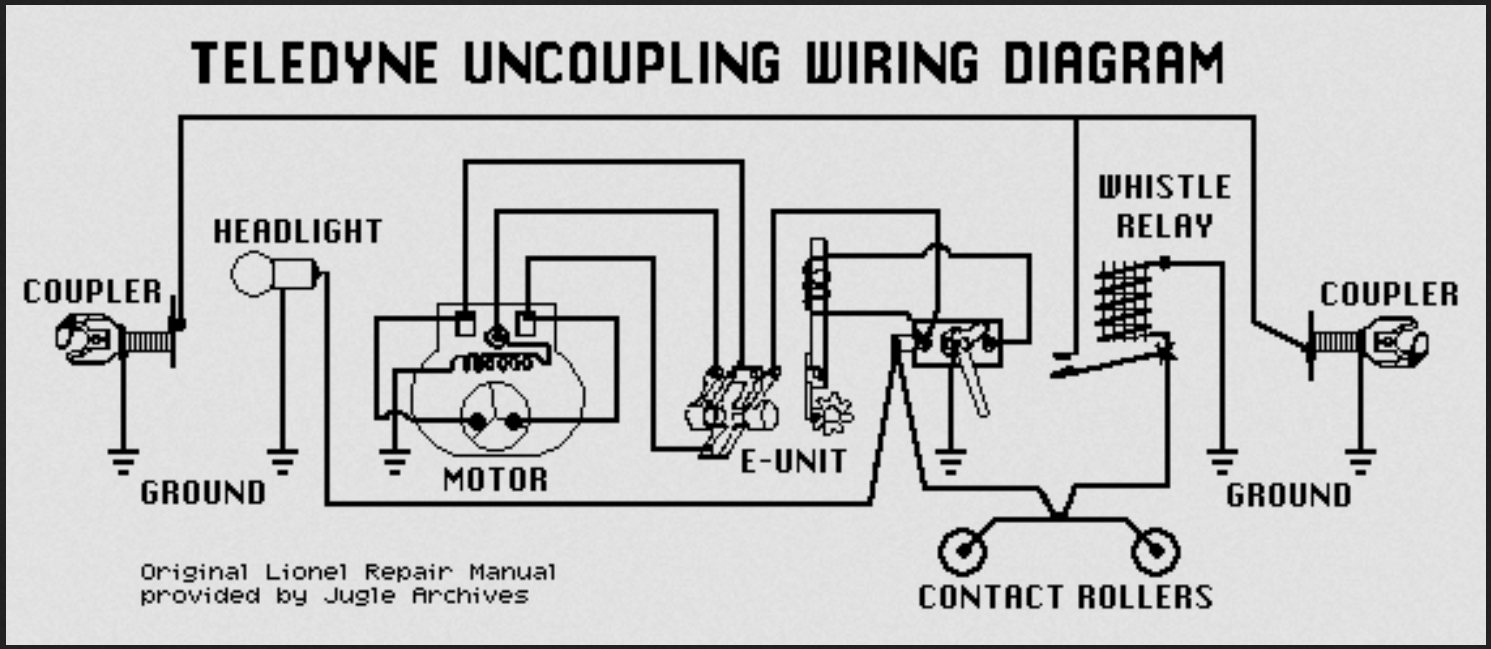
However, even if I'm more or less right so far, I have *not* been able to figure out how the DC offset voltage actually triggers the whistle or horn. It appears the old school whistle tender has a "DC relay" that in turn sends track voltage directly to the motor driving the whistle when it is triggered, but I have not been able to figure out how a "DC relay" is not also triggered by the AC track voltage -- sure, it might chatter like crazy, but I can't see why the relay *only* seems to react to the DC offset voltage. IOW, I can't see how the DC component is separated out from the AC to power the relay.

My goal is to help find a simple method to separate out the DC component, normally intended to sound the whistle or horn, to instead power a 5 VDC motor on a car to dump a load when, say, the "whistle" switch on the transformer is activated, then use the opposite polarity of the "horn" switch activation to reverse the motor's direction to restore the dump pan to its original position. My old-school electronics brain immediately went to using a healthy inductance choke in series between the track and the DC motor, which would in theory tend to block the AC component yet still allow any DC offset to flow through to the motor, but AFAICS Lionel did not use anything like that in their whistle/horn activation system. Also, I'm still not sure/have not yet confirmed the DC offset they used is the right voltage with enough current capacity to power the (fortunately relatively small) DC motor that needs to be powered. Any help would be greatly appreciated, even if it's only to clear up my confusion! Thanks . . .

Original Post

Replies sorted oldest to newest

@Steve Tyler posted:
Part 2 of your question.

My goal is to help find a simple method to separate out the DC component, normally intended to sound the whistle or horn, to instead power a 5 VDC motor on a car to dump a load when, say, the "whistle" switch on the transformer is activated, then use the opposite polarity of the "horn" switch activation to reverse the motor's direction to restore the dump pan to its original position. My old-school electronics brain immediately went to using a healthy inductance choke in series between the track and the DC motor, which would in theory tend to block the AC component yet still allow any DC offset to flow through to the motor, but AFAICS Lionel did not use anything like that in their whistle/horn activation system. Also, I'm still not sure/have not yet confirmed the DC offset they used is the right voltage with enough current capacity to power the (fortunately relatively small) DC motor that needs to be powered. Any help would be greatly appreciated, even if it's only to clear up my confusion! Thanks . . .

Again, while it's a DC motor, you cannot directly using a single device- because you need 2 important functions!!!!

#1 you need to regulate the DC voltage to 5V (or maybe slower/lower) for that motor

#2 you need a device to detect the DC offset signal- and close a relay contact or fire a transistor

Edits with corrections:

Rob's original answer using a DC whistlePCB is a good one- but caution for your application- that outputs UNREGULATED DC when triggered. So it does some of the things you need- detects the DC offset, fires a transistor, and uses a diode to create half wave DC power from AC track power- but it's unregulated voltage output and is proportional to the direct track power voltage. Your 5V motor might spin too fast or be burned out with direct connection to the output of the DC whistle board.

Example AC input, DC output regulated adjustable voltage board.

Key specification- 35V input maximum voltage- because even though we use typically 18-21V AC RMS max, peak DC rectified voltage is higher- hence 35V rating for input.

Search term for modules "AC/DC to DC Step Down Buck Converter AC 5-30V DC 5-48V 24V 36V 48V to DC 2.5-35V 12V Voltage Regulator Board 2A Adjustable"

Couple of ways to skin this cat:

Oldschool- use a shaded pole whistle relay for detection. Take the AC output, and feed that into a rectifier to convert AC to DC, and then a DC regulator to regulate 5V for the motor (there are combined regulators with a rectifier modules out there).

Newer transistor method- use a modern DC can motor whistle board, and a second regulator board to regulate the voltage. Caution, if using a DC input expecting regulator, additional DC filtering and ensuring polarity on the input from the whistle board might be important. IMO good to just use one of these AC input regulator modules, and then way easier and no concern of polarity.

Attachments

Images (1)
  • mceclip0
Last edited by Vernon Barry

Again, go with the link Rob posted to the previous topic on theory of operation of the shaded pole relay.

https://ogrforum.com/...31#41835032951843031

Either way, relevant to the discussion- the facts remain:

The DC offset on an AC waveform is just a signal to tell something to turn on. You are not extracting this DC offset and powering a motor with it.

You specifically stated a small 5V motor, and very likely, you need some form of regulated DC power for that motor- not raw uncontrolled track voltage. Whistle relays and whistle PCBs are simple devices and do not contain a regulator for the output DC voltage when triggered. You likely may have to install a regulator on the output of any triggering device (relay or DC whistle PCB) to again, regulate this output voltage to better control the speed of that motor.

That's still a nifty trick to activate the whistle/bell features. I have to read that post on how it works because I think this would be a useful thing, even if it's just to activate a relay on a car that has more real estate for animation. That's the main limitation of making the slag cars animated: you can't hide very much. A box car is a box car and a flat car could have a conveniently placed crate on it. I think using the whistle/horn button in a boxcar to open and close a door would be cool. But would it activate the whistles/horns of active locomotives on the layout?

I can confirm the converter board @Vernon Barry posted works perfectly. I connected the 18VAC track power to it and got 4.8VDC out. It worked very well. It's just too bad we can't get that board in a slightly smaller package.

Thanks for everyone who has contributed so far -- a wealth of info to help me backfill my ignorance/misinformation!

Let me see if I correctly understand what's been said so far:

- First, as I had surmised, the old-school whistle tenders do just apply track voltage directly to the coil of the on-board "DC relay", which uses some neat electrical tricks to present a very high impedance to the AC voltage component while allowing the DC offset voltage to activate it and in turn send track voltage to the whistle motor. So, no real separation into AC and DC components, but indirectly a confirmation that using a high impedance device in series with a feed from the track can effectively filter out the AC component while allowing any DC component through. Any thoughts on what choke value would be needed to effectively filter out track voltage AC, yet allow the DC 'whistle/bell signal' component through?

- Second, sorry for my initial confusion about the whistle/horn vs. bell activation. Do I understand the old-school "DC relay" whistle tenders will activate *regardless* of the polarity of the DC offset? ISTM the above explanation (assuming I've understood the comments correctly!) would indicate so, and that polarity only became an issue when the capability to send a second activation signal (for a bell) was desired. ISTM2 that adding a single diode in series with the relay would make it polarity-sensitive, right? Did later models employ this method to make the whistle/horn or bell polarity sensitive?

- Even assuming the DC offset voltage can be successfully filtered and extracted from the track voltage (and even made polarity sensitive), my understanding is that the output will in no way be a fixed DC voltage, but rather will vary with the throttle setting and perhaps other factors. Thus, as several of you have suggested, some sort of buck converter would be in order, to regulate and smooth the DC output. Fair enough, but it occurs that feeding a polarized DC input into a buck converter will destroy the 'signal' component, in that a standard buck converter will happily take *either* polarity and output the same polarity DC voltage regardless of the input polarity. I suppose you could use a pair of diodes to route the (polarized) DC component to one of two buck converters, with their outputs inverted to maintain the proper polarity with the (now regulated) DC output, but this begins to look like it might require *several* additional cars to house!

- Which leads me back to the nifty "new school" (well, relatively!) boards, whether Lionel OEM (but out of stock) or aftermarket, that seem to be just the ticket. Do I understand that such boards will detect the polarity of the DC offset in the track voltage and either activate one of two circuits, or invert the output polarity in response? If so, ISTM this might be a near-perfect solution for this application, especially if the output is a regulated 5 VDC (even if it's not, a suitable relay could control a separate power supply . . . though ISTM we might be running into the multi-car issue again!).

Thanks again for all who've taken the time to comment, and I'll be passing all the info on to the member who triggered my query!

@Steve Tyler posted:
...Do I understand the old-school "DC relay" whistle tenders will activate *regardless* of the polarity of the DC offset? ISTM the above explanation (assuming I've understood the comments correctly!) would indicate so, and that polarity only became an issue when the capability to send a second activation signal (for a bell) was desired...

Correct, the polarity became an issue in 1972 when the first electronic whistles(followed by horns in 1973) were introduced, establishing the convention of a positive offset required for whistle/horn.

A study of the Lionel service literature will show that this was always the intended convention despite many of the schematics showing the wrong polarity for the rectifiers... they were always installed to provide a positive offset even though it didn't matter until 1972.  Somebody replacing a rectifier with a silicon diode following the schematic wouldn't notice their error until a modern piece of equipment was powered up.

The addition of the negative offset was an available feature to trigger bells later on.

@Steve Tyler posted:
...assuming the DC offset voltage can be successfully filtered and extracted from the track voltage (and even made polarity sensitive), my understanding is that the output will in no way be a fixed DC voltage, but rather will vary with the throttle setting and perhaps other factors. Thus, as several of you have suggested, some sort of buck converter would be in order, to regulate and smooth the DC output. Fair enough, but it occurs that feeding a polarized DC input into a buck converter will destroy the 'signal' component

No, not really any destroying... it would be isolated from the track input voltage by the whistle module and further by using a 5V regulator like this (6-24v input) on the output side of the $7 module(or similar) that I posted above.. track AC into the whistle trigger, regulated DC 5v output. The one change to the whistle trigger board recommended would be to change the single diode to a full-wave bridge for full wave DC to the DC-DC 5v converter.

@Steve Tyler posted:
...leads me back to the nifty "new school" (well, relatively!) boards, whether Lionel OEM (but out of stock) or aftermarket, that seem to be just the ticket. Do I understand that such boards will detect the polarity of the DC offset in the track voltage and either activate one of two circuits, or invert the output polarity in response?

The output polarity is the same(red wire pos, black wire neg) regardless of the offset polarity on the track AC due to that diode.  What they do detect is whether there is a positive or negative offset(depending on whether the gray wire or the blue wire is connected to the center rail) and will only turn on the DC output if the correct polarity is sensed. So two modules in one car will have the same DC outputs, but when the blue/gray wires are swapped, one will turn on with "whistle" and the other will turn on with "bell".

The whistle boards that are unavailable can be easily reverse engineered, and some folks have even added a relay to these "home-brews" to have them work on DC and AC whistle motors.

Also check out this earlier thread on whistle control boards.

Last edited by ADCX Rob
@ADCX Rob posted:

No, not really any destroying... it would be isolated from the track input voltage by the whistle module and further by using a 5V regulator like this (6-24v input) on the output side of the $7 module(or similar) that I posted above.. track AC into the whistle trigger, regulated DC 5v output. The one change to the whistle trigger board recommended would be to change the single diode to a full-wave bridge for full wave DC to the DC-DC 5v converter.

Sorry, being a bit hyperbolic. What I meant was that the *information* in the "signal", the polarity of the offset, would be obscured if fed into a buck converter, since regardless of the input polarity, the output polarity would be the same, and rather than reversing direction when the offset polarity reversed as intended, the motor would only turn in one direction.

@Steve Tyler posted:

... since regardless of the input polarity, the output polarity would be the same, and rather than reversing direction when the offset polarity reversed as intended, the motor would only turn in one direction.

Just use two modules, one wired gray/blue, the other wired blue/gray.  They are just the sensing switch, not meant to pass any "polarity", but to turn on the appliance.

@ADCX Rob posted:

Just use two modules, one wired gray/blue, the other wired blue/gray.  They are just the sensing switch, not meant to pass any "polarity", but to turn on the appliance.

I think you may be missing the point. "Changing the polarity" (e.g., reversing the direction of the dumping motor) is the one and only goal of the exercise. IOW, there are not two devices to on-off control, only one, which is polarity sensitive; the goal is to be able to use the positive and negative DC offset to turn the motor on or off, and determine its direction.

There's also this, a do-it-yourself bare PC board with opto-isolated outputs:

     Teledyne Coupler Controller (Build-it-Yourself) | Electric Railroad Company (3rd Rail)

I haven't seen it posted yet in this thread.

Because of the use of opto-couplers, reversing a motor with this using Horn and Bell for the two directions should be relatively easy, needing only four extra common diodes (1N4002?).

Mike

Attachments

Images (1)
  • mceclip0
Last edited by Mellow Hudson Mike

Add Reply

Post

OGR Publishing, Inc., 1310 Eastside Centre Ct, Ste 6, Mountain Home, AR 72653
800-980-OGRR (6477)
www.ogaugerr.com

×
×
×
×
Link copied to your clipboard.
×
×