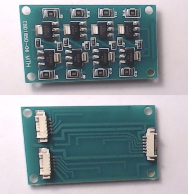
Thinking of converting a PS3 diesel with a dead board to a dummy but would like to keep smoke and lights.  Three questions for our experts and thanks in advance for any ideas:

1) Smoke unit: previous threads indicate this works on PWM and obviously that is gone now.  Is it possible to run the fan and the resistor on a fixed  DC power supply?  A past thread notes that the fan motor is 5VDC, but no mention of the smoke resistor.   I would add an on-off switch.

2) Various locomotive LEDs, headlights, etc.: Does the PS3 board simply power them with a roughly "standard" 2.5 VDC? 

3) Multi color LEDs: It would be nice to have these working but I can't find any documentation on how they were powered by the MTH system.  Are there any good solutions for accomplishing this?  Nothing popped up in a search on ebay.

PS3 diesel exterior wiring

Attachments

Images (1)
  • PS3 diesel exterior wiring
Original Post

Replies sorted oldest to newest

@AGHRMatt posted:

What kind of diesel is it?

30-20316-1 rail king imperial.

Smoke could be run using a tether from the master unit, the PS/3 board will support two smoke units.

Lights could be run from track power.

i was thinking of building a dc supply to handle smoke and lights. The fets on the main board for the smoke unit are dead it appears.

Last edited by hokie71

Of course, without command control, the smoke will run all the time...

I think that was his intent from the get-go and to install a switch to turn it off.

Is it possible to use a small 3v relay wired from an unused lighted circuit to turn the smoke on & off? The concern would be the current required by the coil could be too much for a PS3 LED light circuit.

Last edited by H1000

On the smoke unit:

Normally I would have made that exact recommendation- a standalone PS1 unit, however, I do not know the full intent.

By that, I mean what do you intend to run this dummy with?? If Conventional (say roughly 8-14V track power) then fine. However, when using 18V constant power common with typical DCS command controlled other locos- now we are pushing the upper range of this PS1 unit- especially long term operation. Yes the unit tries to self regulate and is intended for a wide range of typical Conventional voltages all the way up to 18V, that said it's just putting the 2 smoke resistors in series. That has it's limit for long term constant 18V input will run the resistors very hot. So it will smoke like crazy as long as it has fluid, and then begin to cook itself when run dry.

Not all that long ago, there was a topic about using a DC switching regulator for just such a smoke unit.

https://ogrforum.com/...0#171907990311279380

and- where they did use a DC buck regulator

https://ogrforum.com/...0#171907990311279380

On the LED wiring:

Couple of basic things or "rules:

#1 LEDs need some form of current limiting. It's NOT just a voltage, you need controlled current.

#2 Different types and colors of LEDs have different voltage turn on requirements and lesser voltage ones- example red will rob power in parallel from higher voltage ones like white.

#3 Relevant to the above- PS3 LEDs in a loco do not have any in series resistors for current limiting- you are going to have to add them. Again, they are just bare LEDs with wires- no current limiting "built in".

So bottom line, one route is using a constant voltage regulated source- say 5-6V, and then using and adding individual current limiting resistors for each and every LED. The advantage of that is, then you could tune the resistor for a given LED function individual brightness.

I realize this is a lot and everyone may not come to the same exact path. By path, I mean use a constant voltage regulator board, and use individual current limiting resistors for specific LEDs. Additionally, the choice between slaving the smoke unit, or a PS1 unit, or a likely separate adjustable constant voltage source for the smoke unit heat resistors and likely a lower voltage for the fan motor as well.

Edit, also, one could explore powering both the LEDs and the smoke unit from the same fixed voltage source.

Last edited by Vernon Barry
@H1000 posted:

I think that was his intent from the get-go and to install a switch to turn it off.

Is it possible to use a small 3v relay wired from an unused lighted circuit to turn the smoke on & off? The concern would be the current required by the coil could be too much for a PS3 LED light circuit.

I doubt you'd find a relay with a 3V coil that will run on 20MA or less.  I have a relay module that triggers on very low voltages and currents that would operate a smoke unit, it has a 5A relay.

I doubt you'd find a relay with a 3V coil that will run on 20MA or less.  I have a relay module that triggers on very low voltages and currents that would operate a smoke unit, it has a 5A relay.

That would be the better route, it might cost more but you won't be blowing up pricey boards.  I've used a relay in the past like this but that was on a PS2 board and the coil draw was only 60mA.

Good information and thanks to all for the input, with everyone's help, plans are coming together.

In thinking about the various suggestions and tying them into the LED lighting options, I started wondering what triggered the "charging lights" on the locomotive. It may be a bridge too far but perhaps someone has an idea on giving them life in this project. 

The charging light driver board (AE2104037001) appears to have 3904 transistor switching circuits, something like this below).   Based on the wiring in the loco, I don't see a separate component driving the charging lights and it appears the 3904s are triggered by a clock pulse from the PS3 board to turn on the various colors in sequence.  Is there an option to give life to drive these charging lights that I am missing?

  SWAG (scientific wild axxed guess) for the 3904 led switch circuit

AE2104037001 Charging light driver. 

Attachments

Images (2)
  • 102_8458a
  • mceclip0

Charging lights were cycled by the ditch light outputs to create the charging light chase sequence. I'm thinking they used the additional rear ditch light outputs- the last time I traced one of these out.

This board is just transistors and current limiting resistors to amplify and drive the LED charging light strips. This is because again, the PS3 LED outputs are current limited and so this allows multiple LEDs in the sequence strip to "chase" and give the motion.

There are 4 total control lines- resulting in 4 separate groups of LEDs in each strip.

Regarding the chasing charging lights:

This is not golden trusted information. I will have to trace one when I get a chance today. This is based on just me tracing one out in the past and failing to properly capture that documentation (memory only). I think the board is getting the 4 control chase sequence channels and a regulated power source P5V (5V) DC, and then DC ground.

I also think that it required specific chain files from the GEVO or charging light equipped locos (example Christmas and Halloween charging light ES44s) to cause the ditch light outputs to do the chase sequence. In other words, sound file alone is not enough- you have to flash a diesel PS3 board sound file and chain files.

Again, 4 LED output control wires, PCB ground, and I think- not sure, P5V which would be 5V DC???

So, in theory, one could program a 5V micro controller, with outputs to do a chase sequence on LEDs, and then input that into this charging light driver board??

But yes, basically what is drawn as the switch represents a logic high 5V input on the 4 channels of the driver board. The driver board also just duplicates for both sides of the engine- so there are 2 each 4 channel outputs, but they are just duplicates of the input.

Attachments

Images (1)
  • mceclip0

@Vernon Barry "So, in theory, one could program a 5V micro controller, with outputs to do a chase sequence on LEDs, and then input that into this charging light driver board??"

Thanks for the details and .....Bingo- I thought that might be where the project to give new life to the charging lights might be headed.  This dummy diesel may need to wait on that unless we find a simple work around. 

The Arduino Nano would do the trick, just need a 5V supply.  I'd probably be tempted to just lay out a board with the transistor drivers and a PIC processor to drive them, that way you have everything on one board, power supply, microprocessor, and the driver transistors.

Would this be the work around of my dreams?

Where have I heard this:

nothing is so easy as the job you imagine someone else doing......

Great post.  I've converted a few diesels to dummies and added LEDs using track power -- that was easy.  For this dummy (me), adding a smoke unit, however,is beyond my scope.  Would it be fairly simple and, therefore, relatively inexpensive option to hire a tech to add a smoke unit to a dummy powered by the main diesel?  That would be cool do so if the price doesn't kill you. 

@IRON HORSE I may be wrong, but.....

if I read the information above correctly, if you have a newer Pulse Width Modulation smoke unit, it would be very difficult since the PWM part would need to be designed.  If you spend $60 on a PS1 unit that can run on constant voltage, you still risk overheating if you are running at command voltages.  I have given up on a smoke unit for this project. 

@hokie71 posted:

@IRON HORSE I may be wrong, but.....

if I read the information above correctly, if you have a newer Pulse Width Modulation smoke unit, it would be very difficult since the PWM part would need to be designed.  If you spend $60 on a PS1 unit that can run on constant voltage, you still risk overheating if you are running at command voltages.  I have given up on a smoke unit for this project.

Those ps1 units will be fine at 18 volts. They were actually designed to run at 22 volts (max Z4000 output voltage). They will crank a lot of smoke but some 3 Amp diodes inline before the smoke unit will drop the voltage if you want.

Last edited by H1000
@H1000 posted:

Those ps1 units will be fine at 18 volts. They were actually designed to run at 22 volts (max Z4000 output voltage). They will crank a lot of smoke but some 3 Amp diodes inline before the smoke unit will drop the voltage if you want.

That is good to know.  I wish MTH had a half price sale coming up like Lionel does....

Relative to the PWM smoke units, I wonder if it is possible to put them on a buck converter or similar and find a sweet DC voltage spot where the unit would run and emit smoke, without damage.  If I remember the smoke fan motors runs at 5v DC- no idea what the resistor needs.  That would get smoke for a $5 buck converter parts cost and minimal installation time.

@hokie71 posted:

That is good to know.  I wish MTH had a half price sale coming up like Lionel does....

Relative to the PWM smoke units, I wonder if it is possible to put them on a buck converter or similar and find a sweet DC voltage spot where the unit would run and emit smoke, without damage.  If I remember the smoke fan motors runs at 5v DC- no idea what the resistor needs.  That would get smoke for a $5 buck converter parts cost and minimal installation time.

It's actually very easy to power a smoke unit if you don't mind it running continuously.  As you say, the buck converter would be one ingredient.  A standard PS/2 or PS/3 smoke unit will require voltages in the range of 6-7 volts for the smoke resistor, some series diodes off that will drop the voltage for the smoke motor into the 4-5 volt range for proper operation.

It's actually very easy to power a smoke unit if you don't mind it running continuously.  As you say, the buck converter would be one ingredient.  A standard PS/2 or PS/3 smoke unit will require voltages in the range of 6-7 volts for the smoke resistor, some series diodes off that will drop the voltage for the smoke motor into the 4-5 volt range for proper operation.

The rest of the story.  Project done, I now have a rail king dummy GEVO with oscillating colored LEDs, head and tail lights, marker lights, and a smoke unit.

I was able to put in a small slide switch to cut off the smoke unit and used the buck converter with the suggestions above to power it.  At York, I found this "oscillating" 10 LED unit for $20 from Evan Design.  the unit runs on 5-19vac and comes with white LEDS. I used clear Tamaiya paint to add some color-  5 lights on each side.  Not quite the original but something to add some flair for train shows.

Attachments

Videos (1)
M2U00956
Last edited by hokie71

Add Reply

Post
The DCS Forum is sponsored by

OGR Publishing, Inc., 1310 Eastside Centre Ct, Ste 6, Mountain Home, AR 72653
800-980-OGRR (6477)
www.ogaugerr.com

×
×
×
×
Link copied to your clipboard.
×
×