We are putting together a list, hopefully of all of the various electronics projects that have been designed here on the OGR forum. This has been discussed a time or two, but I don't think anything has come of it, so this will be a start.

There are several very good electronics projects posted here that can sometimes be difficult to find. The plan is to try and gather up the various project info here in this thread. All this info will then be compiled into a list of the various projects with links to the threads detailing each project.

After we get a good list going, the compiled list will be posted in the ' ELECTRICAL REFERENCE MATERIALS & MANUALS ' thread which is a 'Sticky' topic at the beginning of the Electrical Forum. The final list will then be updated from any additional or future applicable posts to this thread.

We hope everyone will use this thread for all discussion to keep the final list in the Electrical Reference thread as uncluttered with comments as possible.  So, we are asking that you please use this thread for all discussions about the list.

My thinking is that we should keep this list to just the actual projects that have been designed in various threads here on the forum. As in the ones with an actual circuit, PCB, parts list, schematics and any other files related to the project.

I realize there are many, many excellent wiring diagrams for everything imaginable posted here on the OGR forum that are also very valuable. But I think trying to keep track of all that would be an overwhelming task and almost impossible to put together and/or maintain. So please keep any suggestions to the actual electronics projects that were designed here in a thread(s).

All comments and suggestions welcome and thanks for any and all input.

Last edited by rtr12
Original Post

Replies sorted oldest to newest

Here's one to get started with. It's kind of a mix match of 555 timer projects:  Semaphore and 555 Timer Circuit 

It goes back a few years, covers some different things done with 555 timers and CD4017 counters and ends up with a 4 way traffic light signal board. (It's also where this thread originated.) I'll re-read it all and try to give a better description of all that is covered. 

Just had another thought about this list. I was originally thinking about only posting links to these threads, but now I'm thinking it might be a good idea to post any related project files here along with the links to the threads. 

One important concern would be keeping the files current if there were changes or updates after something had been added to this list. Causing problems in trying to keep the files current with the latest versions. On the other hand, some of these projects have remained as they were designed for quite some time? Also, we probably wouldn't want to add anything that was still in the works, but wait until it was completed?

Any thoughts on this are most appreciated! 


Here's another project link. This is Ardian!'s AGHR Telemetry car for checking DCS signals around the track. AGHR DCS Telemetry Train Rev 7

This is probably not a beginner's project, and requires a bit of expense and a few parts so it's not exactly an inexpensive little PCB project. It also requires an Arduino and a Raspberry Pi (C code is included). It does really look like a very nice tool for diagnosing DCS problems as well as a pretty neat thing to have for a club or larger layouts. I think it would be fun to have on a smaller layout too (as in mine!). 


rtr12 posted:

Just had another thought about this list. I was originally thinking about only posting links to these threads, but now I'm thinking it might be a good idea to post any related project files here along with the links to the threads. 


Tom I am wodering if this is a good idea? I am thinking it would be difficult to keep updated files in two places, and this might go sideways on us. I think the original idea of a link to the thread where the circuit is developed and ultimately posted is the way to go. But that's only me. 

Rod

OK so here is a link to a handy truck or railcar mounted Track Spike Detector which you can haul around your layout and it will warn you if any damaging voltage spikes are detected by flashing two red led's. It is compact and easy to build, a great beginner project. Circuit originated by Stan2004.  Boards can be ordered easily online using the included Gerber files.

Link; https://ogrforum.com/...track-spike-detector

Rod

Last edited by Rod Stewart

Here is a link to a pretty neat board that will sequence 2 or 3 Aspect Block Signal LED's that are wired common anode. This wiring method is typical of offshore aspect signals such as those sold by wehonest and JTD. This is perhaps a medium challenging build using all through-hole assembly. A Bill of Material is included for both all domestic components, or all offshore including circuit boards. User notes are included to help the builder decide on several different assembly options and methods of use. Many folks contributed ideas and suggestions to this project, including Stan2004, gunrunnerjohn, cjack, RTR12, and Rob Paisley who operates a site called Circuitous. The boards can be ordered easily online using the included Gerber files.

Link to Thread: https://ogrforum.com/...or-common-anode-leds

Direct link to Post containing the build files:files

Rod

Last edited by Rod Stewart

I am having the same thoughts about posting the actual project files and keeping up with changes. But, after looking at a couple of project threads they were fairly old and had not changed since they were finalized. So I am now thinking that might not be as bad as I thought. There will also be links to the threads, so a note could be added to be sure to check the thread for updates. Maybe adding the date the files were added to the list would be a good idea as well?

What and or where to link to in the threads is something I hadn't yet thought of? This all sounded fairly easy at first, but might be a bit more involved than I first thought? When going back through the first thread I posted above, I discovered quite a bit of extra information that I had totally forgotten already. But is was very good info for someone trying to learn about these circuits. I relearned a thing or two myself by rereading that thread. 

I think I am now leaning toward a link to the main thread and maybe adding another link directly to the post containing the project files. Doing that and adding a note to always check the original thread for current versions might cover things pretty well.

How does that sound? 

Here is the link for a 1 Amp LED/Incandescent Lamp Flasher Using Mosfets from about a month ago. This circuit flashes two lamps alternately at about 1 Hz, the speed can be varied by using slightly different value components. It is easy through-hole assembly and the cost to produce them is very reasonable. Boards can be ordered online easily using the Gerber files included. This board works equally well with leds or bulbs such as the PW #154 Lionel crossing signal, which has no internal circuitry of its own. BOM's and User Notes are included. 

Link: https://ogrforum.com/...-board-using-mosfets

Direct link to build files: files

Rod

Last edited by Rod Stewart

Here is the lower powered LED Crossing Signal Flasher Module suitable for any dual led crossing signal that does not have built in flashing circuitry. Again the suggested values give you about a 1 Hz flash rate, but this rate can be changed by using different value resistors as detailed in the thread. Very easy to build.

Link: https://ogrforum.com/...-module-with-gerbers

Rod

Another project courtesy of GRJ, Automatic cab light control, Rule-17 lighting, and smoke intensity control for diesels. 

Link: https://ogrforum.com/...rol-lighting-in-loco

The module senses voltage on the loco motors, and when the loco is stopped, a relay turns on the cab light, dims the front and rear headlights, and reduces the smoke intensity.  GJR included Gerber files and BOM.   This uses surface mount components.  He includes a wiring diagram for TMCC diesels.   I believe it could be adapted to other control systems.  Boards at OSH Park were 3 for $4.40 in 2018.

He also included a smaller, cheaper simpler version without the smoke effects. The smaller boards were 3 for $2.15.

Bob

Last edited by RRDOC

Another of grj's great little circuits is the DIY Constant Current Passenger Car Lighting Module linked below. These are an easy to build module with only 6 components, and easy through-hole assembly. Very nice beginner level project. (If I can build them, anyone can! ) Cost is less than $3 a board, and could be reduced with all offshore parts to about a buck.

Link: https://ogrforum.com/...ighting-module-files

Rod

Last edited by Rod Stewart

I like the converging format in the last few posts...a clear bold title of project, a 1-paragraph description, a link to the OGR thread(s) for reference/background.  Would be neat to also include 1 or 2 (at most) photos whether of the 3-D rendering or an actual built board, and a rough cost which I realize can be all over the map depending on where you buy the PCB, whether you use eBay/Asia parts, etc.  But I realize it takes a lot of editorial effort to manage such a list! Nothing is so easy as the job you imagine someone else doing.

Some other OGR projects that come to mind include: 1) DCS Perpetual Barking Watchdog, 2) TIU output level tester, 3) TIU TVS clamp board of which I believe there were 2 versions, 4) TMCC signal booster/tester, I'm a little fuzzy on this one, 5) and at least one LED conversion board for passenger cars.

Then, since we are still kicking around what this list should or shouldn't include, I wonder how to deal with the projects that repeatedly come up but never seem to cross the finish line as far as I know.  For example, a latching relay board for Tortoise switch machines, or an optical isolated trigger board so you can use the 99-cent eBay DC relay modules with AC O-gauge insulated-rail triggering.

Another issue.  So if someone stumbles across the list and wants to buy 1 or 2 boards whether assembled or as a kit, who do they contact?  It seems there have been a couple of threads where the OGR moderator justifiably swooped in and said such a request should be posted in the Want-to-buy forum where I'd think it is not likely to get a response (IMO).  Likewise, I can see how this list could end up looking like a For Sale forum which would/should surely get shut down.

Last edited by stan2004

Thanks to all who have added projects so far. It's really a big help in putting this together.

Stan, I agree on the bold titles, I like that format too. Rod has also been helping me offline, we are kicking around ideas on all the little details. But, discussing here is good too and also welcomed and appreciated. 

For the PBW, TIU Output Tester, I just wanted to make sure it was ok with GRJ to add these and gave us the ok last night. So I do have those on the list to add as well as the TIU TVS Clamp board. Thanks for defining that one, I was wondering what to call it. As for the Passenger Car LED board, would that be the one that Rod just posted? 

I don't know about the TMCC Signal Booster, I think GRJ may still be offering those so I'll ask him on that one too. 

For the often discussed, but never finished projects, I think those would be good ones to try and finalize. I might be in for something like that after I get caught up with this list. Rod may be willing to assist as well, I think he enjoys this stuff almost as much as I do? 

As for the kits of just a couple PCBs and parts, that would be nice, but would be quite a bit of work for one person to manage all these different projects I think. I was thinking of these as more along the lines of being all DIY type stuff that would maybe get others interested in the electronics part of the hobby. Although, I can't argue that having kits available would be a great idea for folks that want them. I do think it's something for consideration and cold possibly be worked on or worked out at some point in the future.

Also, I wasn't aware the moderators had stated these things should be in the for sale forum? I had considered posting the TIU Output Tester and the PBW info on the for sale forum (still sitting on several of each and orders have dropped off). But, I was considering this more of a service to forum members and it's all being done at cost. There's no profit so I wasn't really considering it to be selling (IMO anyway). In fact it's actually the other way around, I'm somewhat in the hole. But, it's kind of fun, I enjoy it, good learning experience, helps other forum members and keeps me off the streets. 

I agree about the for sale listing, it would quickly drop off the radar and be forgotten. I don't think anyone would gain from that. Maybe it can all be worked out, but sometimes I'm also a bit overly optimistic... 


Here is a link to my AC-DC DIY LM317 Voltage Regulator Module build files, which I posted separately a short time ago. Again this is a small inexpensive easy to build, very versatile little module, which offers DCS interference protection and is ideal for engine or railcar installation. With offshore parts it cost less than a buck to build! 

Link: https://ogrforum.com/...t-module-build-files

Rod

Ok, here are links to the TIU Output Tester (Adrian!, GRJ, Stan 2004) and Perpetual Barking Watchdog (GRJ, Stan2004) timer. And here is the Redesign thread (most current) of the PBW. The first (Perpetual Barking Watchdog) thread details the design process and related info. The Redesign thread only has the changes made for the second and current version. 

The TIU TVS clamp board (Adrian!, GRJ, Stan2004) thread is here. 

The final list will give credit to all involved in the different designs of these projects, but some I will need to go back through to be sure no one gets missed. It's been awhile since I have read many of these threads and I may be missing some of the contributors to the projects.

Thanks again to all that are adding to the list!

Yes Tom, the DIY Constant Current Passenger Car lighting link that I posted earlier is linked to a new post of earlier today, that comprises the build files from the 7 page long topic called something like "Another LED Passenger Car Lighting Question", which was started in late 2016. I am pretty sure this is the project that Stan is referring to.

Stan I also like your idea of including an approximate idea of costs in the link posts, so I have started to do that in my contributions.

As for small quantities of boards, OSH Park of course builds boards in lots of 3, and as long as they are not much more than an inch in either dimension they are not too expensive. For larger boards it is definitely better to go offshore and get 5 or more. Even if you use only 1 or 2, it will still be less expensive.

Tom I am certainly happy to help out with further development and bringing to fruition some of those never-never projects. Lets see if we can work on that offline and prioritise the list a little.

Cheers, Rod

Thanks Rod, I took a look at it and thought it might be what Stan was referring to. Somehow I didn't have that one saved? I guess I miss a few here and there.

I also agree pricing is a good idea too, but it might take a while to put that together for everything in the list.  I suppose including the recent chart with the different PCB makers and their pricing would be good to have as well. 

I thought you just might be interested in another project or two.   I would also be interested in some of the never-never projects, if I haven't gotten myself in over my head already on this list. Lots of good help here so far so it might not be too bad. I think there is enough info posted here to get going on the finished product.  

Track Transient Spike Detector - Circuit design by Stan2004 - Added by Rod Stewart

Truck or railcar mounted Track Transient Spike Detector you can haul around your layout. Two Red LEDs will flash when a spike is detected. It is compact and easy to build, a great beginner project. Uses all Through-Hole Components and requires only a few parts. Gerber Files are included for PCB ordering.

Link to Thread: Gerber files for Stan 2004's Track Spike Detector and a Link Directly to Project Files Post

Spike Detector SchemSpike Detector 3D

Attachments

Images (2)
  • Spike Detector Schem
  • Spike Detector 3D
Last edited by rtr12

The above is posted as a sample only for the final list. Posted for opinions. I know it's missing parts list and approx. parts cost, just a quick sample. 

The plan was to make it as brief as possible and include pictures for an overall idea of the project. My thoughts were that anyone interested in the project could then go to the linked thread or post with the project files for further information. 

My first thought was to add final pictures of the whole project, schematic, PCB layout, 3D pic, etc. (if available). Then I decided to try a sample post here and realized just how long the entire post would be by adding all the pics.  I'm now thinking that using only the 3D picture might be sufficient for a brief description and idea of the project. Downsizing the 3D pic might even be something to consider as well? 

I will also go back through these posts so far and see if I missed anyone's suggestions, I am sure I probably did.

Track Transient Spike Detector - Circuit: Stan2004 - Added: Rod Stewart

Truck or railcar mounted Track Transient Spike Detector you can haul around your layout. Two Red LEDs will flash when a spike is detected. It is compact and easy to build, a great beginner project. Uses all Through-Hole Components and requires only a few parts. Gerber Files are included for PCB ordering.

Link to Thread: Gerber files for Stan 2004's Track Spike Detector and a Link Directly to Project Files Post

Spike Detector 3D

Attachments

Images (1)
  • Spike Detector 3D
Last edited by rtr12

Tom suggested this might be a good place to re-attach my Quick-Start PCB Design-Fab Notes Word doc for anyone who might be interested in dabbling with DipTrace and pcb board design. It is not comprehensive at all, but should help any newcomer get started. My first few stabs at DipTrace were a pretty bumpy road, but I got a lot of help from grj, as well as Tom; and a lot has been learned through the School of Hard Knocks. 

If you simply download and install DT, then open it, you will be looking at a pretty boring empty black screen. Not very exciting. But I am also attaching two working Diptrace files for the DIY LED Flasher Module; for which the gerber file was linked earlier above. This is so anyone can load the file and simply play around with it to get some DT experience. After you install DT, simply click on the red diamond file (.dch) attached (after downloading it) and you will have the circuit on the screen.  Way more interesting. 

The .dip file is the board layout file that would be created from the circuit drawing file, it's included just as an example. These are the exact same files that I used to create the gerbers from which the boards are built. Have fun!

Rod

Attachments

Last edited by Rod Stewart

Great idea to include some sample files! Those will be a BIG help to any beginners. I think everything here in your post will sure help anyone wanting to get started with DipTrace, drawing schematics and even getting some PCBs made if one wants to pursue it that far.  

I can relate to exactly what you are saying with the blank DT screen when first installing the program. It was quite difficult for me to try and figure out what to do next!  I ended up closing it out, waiting a few days or weeks and then trying it again. Did that several times before I finally got going. It was some sample files from GRJ that finally got me over the hump and starting to try different things in the program to begin learning. Unfortunately, I am still attending that 'School of Hard Knocks' though, but hoping to improve my grades! 

Thanks Bob for the kind words. I should mention that these Quick Start notes are really a work in progress. Almost everytime I use DipTrace I learn something new, and update the doc accordingly. It seems to be getting longer!

To that end I would ask anyone who finds anything that should be added, or modified, if you could let me know either on the forum or directly by email, that would be much appreciated. Then in the cooperative spirit of this forum, we can roll that information out for all to use. My email is in my profile.  Thanks!

Rod

This is a great undertaking - kudos to you and to all the folks that have contributed expertise, circuit designs, comments, etc.  Are you planning to incorporate any "outside" links as part of this effort?  While I am sure there are (many) others, the one I have found quite useful is Rob Paisley's 'circuitous' website.  I suspect you already know about his work but you can find it on the google machine (I didn't want to incorporate a link here lest it might not be what you want to do).

Your effort will be very helpful to the OGR community

Thank you for the kind words! We are hoping more folks might develop a little interest in the electronics part of the hobby and maybe even try tackling a project or two from the list. 

Rod Stewart mentions Rob Paisley in the post about his 2-3 Aspect Signal project above in this thread. A link to Rob's website will be included in the final list in the description of Rod's signal project. Rob actually helped make some changes and fixes to that project. I certainly agree with you (and I'm sure Rod will too) that Rob's website does contain a wealth of information on model RR related electronics projects and he is also a really nice and helpful person!

Here's a link (below) to the Projects List post in the Electrical Reference Materials & Manuals thread.

Electronics Projects Developed on the OGR Forum by OGR Forum Members

I believe the list is complete with links for all the projects that have been suggested here. There are still small some pieces of information to add/edit which is mainly coming up with pricing for a couple of projects. 

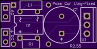
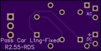
Passenger Car Constant Current 12V LED light strip driver (fixed resistor)

3D Board View R2.55

2 layer board of 1.10 x 0.55 inches (28.0 x 14.0 mm)

IMG_2079

This is another version of Gunrunner John's Constant Current LED driver module.  This was one of John's early designs that he had shared with the forum and on OSH Park.  I had contacted Rod Stewart with some questions about ordering boards and after tossing around some ideas, he re-designed the board layout to allow all components to be top mounted and to allow wider pin spacing and separating the AC and DC connections. The module rectifies and filters AC into DC and regulates the current as required by LEDs.  By changing the value of the resistor (R1) on the board, the level of lighting can be set. So, unlike John's adjustable module you need to figure out what light level you want, then build your modules with that selected value for R1.  I don't like my cars overly bright, so I use a 47 Ohm fixed resistor that gives me my desired light level when driving 30 LEDs (approx 20” of light strip).  For those who like brighter cars, they can use 33 or 30 Ohms.  Shorter light strips may require higher resistor values.  Minimum is 22 Ohms.
Note that these boards have a similar footprint as John's modules sold through Hennings Trains, but his smd component modules are not as tall.  Also he uses a regulator with a bendable tab that can be bent at 90 degrees to lower the height further.  And adjusting brightness is very easy with his modules.
This constant current module will take 10-18VAC (eg. model train track power) and output DC to drive 12V LED strips. It has Flicker-free operation and DCS signal protection.
Boards can be ordered directly from OSH Park through this link.  3 boards are $3 shipped.  Parts can be sourced for $1 per board with parts from Asia.
I want to thank Gunrunner John and Rod Stewart for their tremendous contributions to the forum and the hobby and for their permission to post this design.

Attachments

Images (2)
  • 3D Board View R2.55
  • IMG_2079
Files (1)
Last edited by RRDOC
@RRDOC posted:
These modules have a footprint of 1.1" x 0.55" compared with John's modules sold through Hennings Trains that are  1.125” x 0.75”.  It takes the same components as other versions of John's modules except no potentiometer.

What kind of ruler are you using?  From the CAD file for my commercial version.

Also, one of the important dimensions is the height of the module, I use a specific regulator that has a bendable tab so I can shorten the height of the module to 1/2" high to minimize the total footprint.  That's why the regulator is in the middle of the board.

Attachments

Images (1)
  • mceclip0
Last edited by gunrunnerjohn

Add Reply

Post
×
×
×
×
Link copied to your clipboard.
×
×