Ron045 thanks for the reply!  When I was working on the room before I built the benchwork I did contemplate the ceiling.  I finally decided that I was going to leave the ceiling open and never put anything else up there.  I wanted access to the pipes and HVAC and due to the height of the joists and the way the utilities are mounted any kind of ceiling would be a challenge.  So I opted for the industrial look. Thanks again for the suggestions and feedback, all very helpful!

Michael

Looks Great, nice job.  I like the backdrops, they add a lot to the layout.  I might suggest you think about painting the entire ceiling over the layout flat black, it will really disappear, and all the focus will be on the layout, especial with your outstanding backdrop.

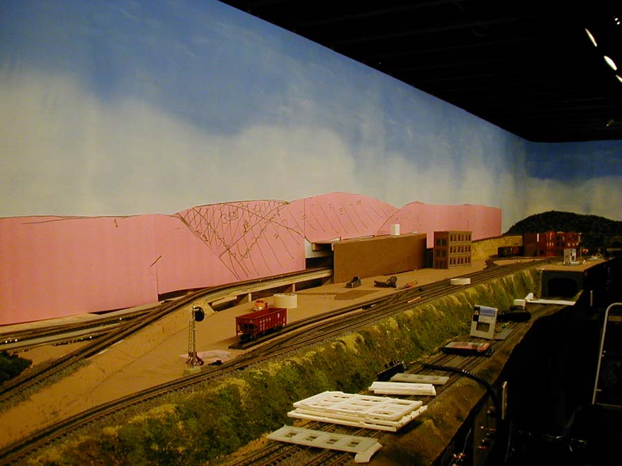
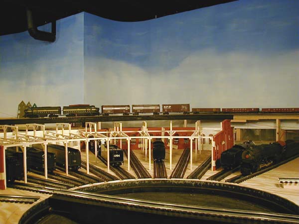
Here is an early Photo of Bob Bartizeks Layout, you can see how the ceiling disappears and the focus on the layout.


Last edited by Rich883

Thanks for all the great input, Tom Tee, Mark and Rich883.  I wasn't going to paint the ceiling but now I can see that I might regret that decision down the road.  The flat black definately finishes it off and makes the layout stand out.  I will contemplate that decision before moving forward with anything else.

 I will re look at my grades and make sure I am happy with them and that's good advice about the pop up holes.  I don't want any skin rashes!

Michael,

First, congratulations on such a fine start to your layout! Well done! I like the thought that went into the track planning. I also love your choice of backdrop. Pennsylvania it is. 

Let me second Tom Tee's thoughts and suggestions. Before you go any further, please take care of the ceiling! Flat black paint works wonders at hiding distractions. It also has the added side benefit of sealing the wood above the layout. This can dramatically lower the dust accumulation down the road. It also has the added effect of maintaining accessibility while hiding everything in plain sight, including that ugly aluminum covered insulated duct work. If you go this route, be certain to adequately protect your backdrop. Black paint will really spoil it...

Here is a shot of my train room. I am VERY happy with the black ceiling and track lights. The fluorescent lights you see in the picture have since been disabled. The room is lit by only the track lighting. This does an excellent job of drawing attention to the layout, and nowhere else.

Chris

LVHR

A0050324

Attachments

Images (1)
  • A0050324

Good evening everyone,

It is finally time for an update after some of the progress of the past couple months.  Progress has been slow due to an ongoing family health problem, but I wanted to share what we have done up to this point.

First off I have decided upon a name for my railroad.  It will be called the "Allegheny Crossing".  I will be updating the title of this thread with that name.  The meaning of this name represents a couple things for me.  First Allegheny describes the general type of area I am modeling after the (Pennsylvania/Western Maryland).  Crossing represents the connection of these areas together but it also represents the bridge that was made when Jesus died on the cross for my sins so that I could be forgiven and spend eternity with Him.  The Lord has given me the ability to create this model railroad and everything that happens with it is dedicated to Him for His glory.

The last time I posted I received a lot of suggestions to paint my ceiling flat black before proceeding.  After thinking about it, I decided to get a painter to come in and do that.  I want to thank everyone for that advice and I am so happy I did that.  It makes all the difference in the world!

After the ceiling was painted we mounted a window air conditioning unit in the room to help keep it cool during the summer.  We also trimmed out the sides of the backdrop with white trim to finish it off.

After that, I re hung all my pictures, posters and signs on the walls to finish out the room decor. 

In addition to that, I built a control table for the transformers and control system components and laid them out on the table.

Next up I will be mounting a board under the table which will house my TIU, AIU's and terminal blocks.  After that it will be on to the first track work/testing trains FINALLY!

Here are a few pictures of the completed room and progress so far.

20201031_211407

20201031_211601

20201031_211448

20201031_211532

20201031_211754

20201031_211638

Attachments

Images (8)
  • 20201031_211407
  • 20201031_211407
  • 20201031_211601
  • 20201031_211448
  • 20201031_211532
  • 20201031_211754
  • 20201031_211754
  • 20201031_211638

With trackwork being the next major project on the layout I wanted to gather some advice on order of operations and best practices/tips/tricks.

As stated before I am using gargraves track, Ross switches, Midwest cork for roadbed under the track and Ross bed for under the switches. 

I know it is important to take my time and layout a section and test it for operation before proceeding.  Having said that, this is my first time using all these products so here are a few questions I have.

1.  Do you layout track and roadbed at the same time?

2.  Do you secure each section of track to the table as you go along or wait till an entire loop or operational section is completed and tested before securing it to the table?

3.  Do you paint the roadbed a color similar to the ballast you are going to use so it blends in better or is that overkill since the ballast will cover it?

4.  Do you test sections of track with alligator clips on the wire before permanently soldering the wire to the track?

5.  What are best practices to cut and bend gargraves flex track?

Any advice on any of these topics is greatly appreciated!  Thanks.

Michael

Michael, What you have proposed is very similar to what I have done.  The only difference is I should have bought the already formed Ross bed for switches.  I did know they made it, but forgot until I was well under way.  I found I have a harder time cutting cork the way I want now than I did years ago in HO.  Actually in the end, it won't matter because I plan to cover the cork with ballast someday, but that will be a future project.

1. I lay out the track on the tabletop the way I want it and mark the table with a Sharpie marker.  Then I take the track back up and lightly glue the cork down, weighting it or tacking it with tacks I can remove when dry.  I then sand the cork smooth to get rid of imperfections and the rough edge where you peal the two halves apart.

2.  I secure the track as I go along, doing sections at the most 6 feet long at a time.

3.  I tried the Rustoleum gray rock spray paint on the cork before laying track, but the tiny particles of white and black go everywhere.  Several Forum members suggested I go along with a sweeper (vacuum) hose to pick them up, but I am not too coordinated.  Instead, I paint the cork gray with a brush.  With just one coat, it soaks into the cork a bit, and leaves a mottled look which isn't half bad.

4.  I check out everything with alligator clips before making any permanent connections.  This go round, I tried the GarGraves rail pins with jumpers already soldered on, since I find soldering to rail more awkward and frustrating as I get older.  They give good conductivity, but I learned to feed them through a little larger hole than their diameter because the solder joint can break if you put too much stress on them when fitting them.

5. I have trouble bending GarGraves flex because it is so stiff.  Some modelers have suggested gripping it with two hands and bending it around your body.  I have used flex only for slight bends making connections where two pieces of straight or curved track don't fit smoothly.  It's a little more expensive, but does a better job for me and is much less aggravating.  Make sure you wear gloves bending flex.  If you don't get cut, you will at least have sore hands without gloves.

My way certainly isn't the only way, but it has worked well for me.  I look forward to seeing Allegheny Crossing come to life.

Number 5.  Cut and bend gargraves track. Any curve, less than O72, 72" diameter, best to use pre-formed curved sections. Larger curves, a template, to establish a uniform curve.    I used a large compass.   Atlas track screws were used.

Installing track screws every three to four inches.  Ball point is kept on the center rail as track screws are applied.  The curves are developed, in place, each track end has to be cut with a dremel.  Inside rail(s) will be longer on the curves.

Last edited by Mike CT

Mike, That is a great point that you recommend preformed track for any curves less than 072.  My curves are 054, so that helps explain the trouble I had with my early on experiment.  Good comment on the spacing of track screws.  The flex that I did use as mentioned above required closer spacing of screws than preformed track.  One side wants to raise up if there aren't enough screws.  It stands to reason once I observed it.

Mark and Mike,

Thanks for all the good advice.  That's generally what I was thinking, just wanted to make sure I was in the ballpark.  Most of the places where I am using flex track on my layout are to connect small sections between pre-formed curves, switches or straights.  A few places I am using larger pieces of flex track for custom radius curves but I believe they are all 072 or greater.

Do you have a preference on adhesive to glue the cork/foam roadbed to the plywood?  I'm thinking either wood glue or caulk.

Is there a disadvantage to using a brad nailer/pinner to hold the cork in place while the glue is drying?

Thanks!

Michael

Michael, Personally, I just put down a thin bead of carpenters glue under each strip of cork.  It is easy to get a scraper underneath and lift it off for reuse if I goof or change my mind.  I only use caulk on wood connections, and they can be a bear to pull apart if I realize I made a mistake.  You get the idea I make a lot of mistakes.  Mostly because I hadn't thought through some aspect of construction I haven't done before.

I do put in tacks to hold the cork in place, but leave the heads just off the top of the cork, so I can pull them out with a stiff pair of needlenose pliers when dry.  You really need them to keep it in position on curves.  I am thinking a brad nailer may press them down too far and dimple the cork, but I could be wrong on that since I haven't used one.

Mark, that makes sense, thanks!  I'm sure I will make plenty of mistakes as I go along.  My problem sometimes tends to be I over think things before I dive in (especially if I haven't done it before) and it takes a lot longer to make progress.  There is a balance between both extremes.  As they say, failure is the mother of success.

For cutting Gargraves track, use a Dremel tool with a 3" fiber impregnated cutoff disk. Do NOT,NOT, NOT use the little 1" ones that come in some Dremel kits! They are thin and shatter exceptionally easily. Nasty pieces fly exactly where you don't want the to go when that happens! Don't ask me how I know this! BTW, the next 3" disk I shatter will be the first one.

Regarding trackwork: After you bend it, solder your leads to it. I use my 3" disk to carefully rough the side of the rail, underneath the railhead. For the center rail, remove the black. Easy does it, you are literally scratching the surface. Decide if you are color coding your wire. If you do, stick with it! When you solder, use flux! It truly makes the job easy.

Also, I forget if you said whether or not you are planning to use DCS. If you are, please get a copy of Barry's book, The DCS O Gauge Companion. I think he was up to the 3rd edition before he passed away. Read it before you start wiring or laying track! He has a wealth of information packed into the book that will go a long way towards making your layout a delight to operate. Feel free to post your questions here. There are many people willing to help you.

Chris

LVHR

Chris:

Thank you for all the great advice!  I did get 2 of the cutoff wheels that Gargraves sells.  So I will be using those with the dremel to cut the track.

I am running DCS as well as Legacy/TMCC.  I have both of Barry's latest books for DCS and Wi-Fi DCS.  I have read through sections of them a while ago but it will be good to reread and refresh my memory now that I'm ready to actually start building.

I also have all the Black Diamond railroad dvd's which touch on a lot of the construction techniques mentioned above.  It is time to rewatch those as well.

Everyone here has already been an invaluable resource of information for my layout of which I am extremely grateful.  I am sure I will be asking many more questions over the course of construction.  Thanks!

Michael

Last edited by Michael Cimba 040217

Good evening,

Juat wanted to give a quick update.  I have spent the last month or so testing transformers, control system components and engines and getting familiar with using the dcs wifi app and the legacy cab 2 to control everything.  I setup a small test track to test my equipment.  It is definately a leap in technology from my days of running only post war lionel's conventionally, but WOW, all I can say is, it is a very gratifying experience and I can't wait to run the entire railroad. Now that winter is upon us and the yard work has come to an end I'm hoping to have more time to work in the train room.

This weekend's project was to work on the under layout control board that houses the tiu, aiu's, terminal blocks and wiring etc.  I got the board and some components mounted.  I have included a picture of the progress.

20201206_221347

The next project will be to build a second shelf for the main control table that houses the transformers, legacy base and wiu.  Once I get all that stuff mounted, I will be able to lay track and wire up as I go along.

I also included a quick picture of the top of the layout with some track pieces in the general area they will go.

20201206_221528

That's all for now.

Michael

Attachments

Images (2)
  • 20201206_221347
  • 20201206_221528

Michael it really looks great but I would consider a lot more lighting as the layout progresses you start seeing a lot of shadows and dark spots just where you will want to be working and then you will be trying to figure out lighting. Control them from several different switches so when you are operating you can better control the lighting. My layout room has a white ceiling with almost 30 6 inch LED lights and I have shadows and dark areas.


68F66AA0-D5A8-4550-BF06-D282313A3EBADAE8AEE0-B1BB-4E12-8845-466FF49926F835D17F3F-1931-404C-9FFE-1A8793FF5C2C

Attachments

Images (3)
  • 68F66AA0-D5A8-4550-BF06-D282313A3EBA
  • DAE8AEE0-B1BB-4E12-8845-466FF49926F8
  • 35D17F3F-1931-404C-9FFE-1A8793FF5C2C


3.  Do you paint the roadbed a color similar to the ballast you are going to use so it blends in better or is that overkill since the ballast will cover it?


Hi Michael,

Doesn't look like anyone has addressed your #3 question yet (unless I missed it, my apologies if so).

If the ultimate goal is to do some actual scenery, I start out by painting my whole layout surface with a good, all-around dirt color, such as a light tannish-gray, or whatever color represents the locality you're trying to model.  Water-based latex or acrylic paints works just fine for this.  I paint the whole layout surface, including the roadbed.

Then I come back in and paint my roadbed flat black or a flat dark gray before ballasting.  I fully paint the roadbed itself, then I brush out an inch or two minimum on either side of the roadbed.  This is where I let the brush start running a little dry on paint.  By painting the roadbed a dark color, if the ballast gets a little thin in spots, it looks far more realistic than having some bare, unpainted cork show through.  At least in my opinion.

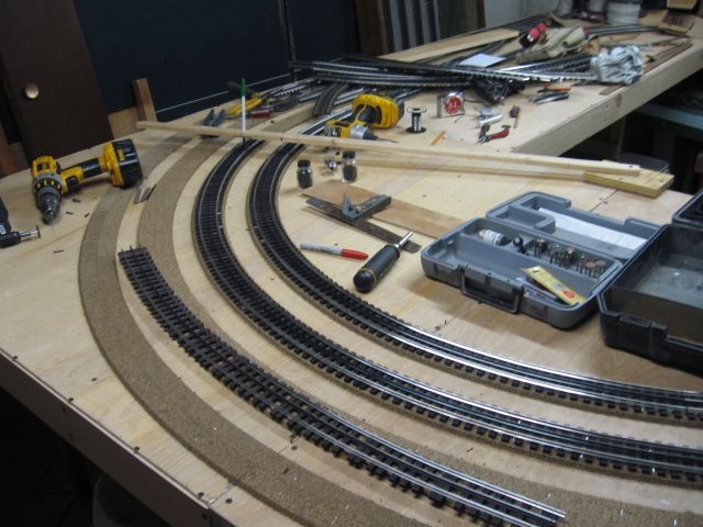
Here's a pic I have showing this exact method.  I still haven't done any track weathering or ballasting yet, but that might happen over the course of this winter.  Note: my roadbed here isn't cork, instead I cut my own from some 3/16" thick foam poster board.  It's probably not as good as cork, but it will suit my purposes just fine in this particular case.

003

Attachments

Images (1)
  • 003

Thank you eveybody for the encouragement and advice! 

RJT:  Thanks for the suggestion on the lighting.  I'm pretty happy with the amount of light in the room right now.  I do have a few shadowy spots, but I'm ok with them based on thr scenery I'm gonna put there.  The lights are on a dimmer so I can create night easily.  I will add some light under the table especially by the control panel so I can see everything under there when I'm working.  Thanks for sharing your layout, I love the room and the layout design!

Mixed Freight:  Thank you for all the advice on painting the layout base and roadbed.  That is all good stuff to consider.  I will be adding scenery and ballast down the road so those are all good things to think about.  Nice looking train by the way!

20201209_222137

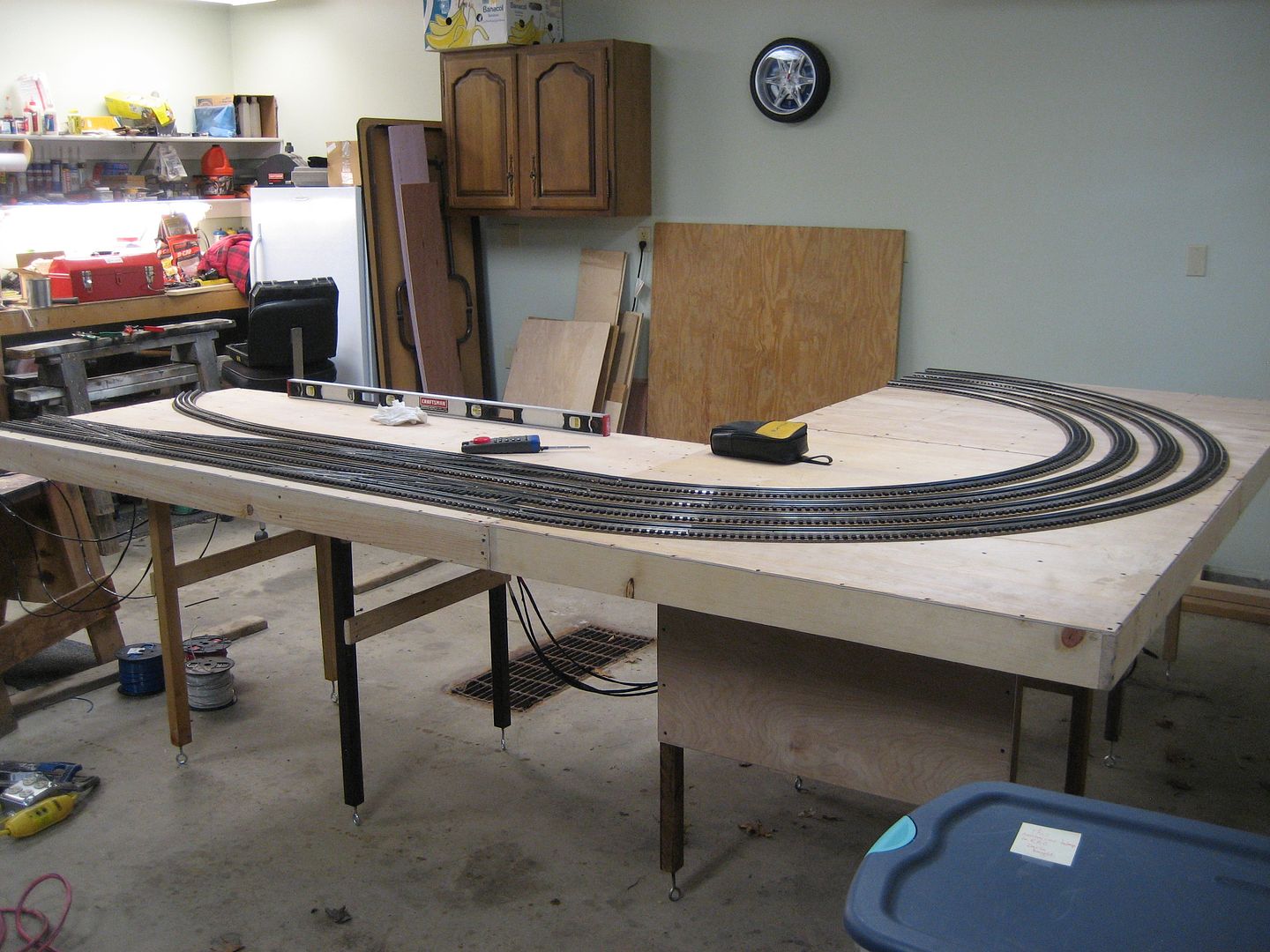
In general I have an order of operations question/dilema.  As you can see from the picture above I have sectional track and switches laid out with gaps where cut sections of track need to go.  I would like to cut the sections of track and assemble them to the rest of the track/switches to check clearances/run trains and make sure the layout works operationally. 

Is it a mistake to do that and then disassemble the track, come back and paint, glue roadbed down and screw the track down permanently? 

I know most of you say to go a section at a time which I also agree with.  But my fear is if I go section by section and glue roadbed down and lay track that I might have alignment problems and then I am stuck because I can't adjust it.

Maybe I'm over thinking this.  I want all my track work to be neat and aligned well and I want to do things in the right order.  I'm probably a little timid because I have never cut Gargraves track before and have never used roadbed before.  I have the layout drawn in rr track software with the track cut lengths labeled.  I also have transfered the layout to the table fairly neatly and acurately.

I am hoping I can avoid/prevent some common mistakes.  Thanks in advance for any help.

Michael

Attachments

Images (1)
  • 20201209_222137

Michael,

I like your approach of cutting and testing first before gluing the road bed, especially with the  curved switches I see you have.  Determining a true minimum O-72 radius through the curved switch with flex track leading up to it is challenge, even when scribed on the bench work.

I ran into this issue with two different O-72/O96 curved switch locations on my layout, where I used track planning software to really maximize my space using minimum radius of O-72, but found issues later on with some of my equipment requiring O- 72 where others engines with the same requirement worked just fine.  I should have spent more time on testing these areas with my all of my larger O-72 equipment before the more permanent installation.  It was messy and a pain to correct later on.

Michael, I cut and fitted my track, marked the location, then lifted it up, and then laid the cork.  I then painted the cork gray instead of black thinking it would look better in the interim before ballasting.  I like to ballast after the scenery next to the track is in.  Personal preference.  Paul's black paint looks good and will be a good base showing depth and shadows if any spot is missing ballast.  I didn't use black because I didn't think of it. 

Thank you eveybody for the encouragement and advice!


20201209_222137

In general I have an order of operations question/dilemma.  As you can see from the picture above I have sectional track and switches laid out with gaps where cut sections of track need to go.  I would like to cut the sections of track and assemble them to the rest of the track/switches to check clearances/run trains and make sure the layout works operationally.

Is it a mistake to do that and then disassemble the track, come back and paint, glue roadbed down and screw the track down permanently?

Hey Michael,

No mistake at all, what you are planning on doing sounds perfectly fine to me.  I'd do it that way, too.

A few extra tips to consider that I can think of right off hand.........................

You might want to temporarily fasten all your switches and preformed track in the picture down to the layout surface, so they can't slide around while you're cutting the flex track to fit in between.  You might try using small nails, staples, or screws placed up against the sides of the rails and ties.  With screws, you could also employ steel or thin wood washers.  For nails or staples, don't hammer them all the way down, you will need to be able to pull them out later.  CAUTION: Be extra careful if hammering close to your rails, these hollow formed rail sections will dent very easily!  Denting the rail on an expensive switch will not make your day!

Start out by fitting and cutting your longest piece of flex track first.  That way, if you mess up, you can re-use this piece at another slightly shorter area and won't waste hardly any track in the process.  Besides, the more pieces you fit and cut, the better you will get at it (it won't take long ).

Having short pieces of fitter track makes good track alignment hard to do.  In some places you probably can't avoid it.  But for example, if you have a space requiring one full length of track and another only a few inches long, then consider cutting one piece of flex track in half and another piece slightly over a half in order to span the full gap.  This will make track alignment much easier in these areas.

If needing fitter pieces in curved areas, pre-bend the track to the proper radius before cutting the fitter piece.  The shorter the fitter piece, the harder it will be to bend it smoothly after it's been cut.

Once all your track cutting and fitting is done, you can hook up some power to it and run some trains over it to check out operation.  Or just roll some freight cars over the track and see how they behave.  Or you can simply eyeball it and make sure all the curves and straights flow smoothly together with no kinks anywhere.  Once satisfied, it's time to get ready for roadbed.  Mark the outline of all track pieces, then remove track in areas where you can start laying road bed.  Don't paint anything yet - you'll cover all your marked outlines!

That's it for now.  Once all your track outlines have been properly marked, laying roadbed is really quite easy.  You don't have to be near as precise as cutting and fitting track.

Hump Yard Mike, Mark and Mixed Freight:  Thank you so much!  That is exactly the "confidence" I needed.  I can really wrap my head around the way you described the process in detail.  All the suggestions, tips and tricks are very useful and practical and give me a good starting point.  All the wonderful folks on this forum make a daunting task seem do able for a newbie.  Thank you!

Michael

I want to wish everybody a healthy and blessed New Year!  Thank you for all the help and advice that has gotten the Allegheny Crossing off the ground.  I couldn't have started without all of you!

I haven't done much on the layout lately that I have to show for, but I have been doing some cleaning and organizing that has needed done.  I repurposed an old hospital medical cart that my grandfather had aquired somewhere into a toolbox/work area/wire cart. The tubes that hold the wire spools came from some old speaker stands I had lying around.  The other side of the cart has plastic bins that are perfect for housing oil, grease, glues, wire tires etc.  I put the cart in the train room during construction, so now I have most everything I need at my fingertips.

20201231_200812

20201231_200750

20201231_200802

I have also been doing some electrical planning.  Thanks to @Mark Boyce and the discussion on the Blackwater Canyon Line for great assistance in this area.  I have decided to use PSX-AC circuit breakers between the transformers and the TIU for extra protection.  I have also decided to put a TVS at every track feed.  I am going to use Wago Lever connectors for my wiring connections. 

Looking forward to hopefully making some noticable progress this year!

Michael

Attachments

Images (3)
  • 20201231_200812
  • 20201231_200750
  • 20201231_200802

Well it is finally time for an update.  I have been busy the past two months finishing construction on my control table, mounting all of the transformers and electronics and wiring up the control table to the control panel under the layout.  I will explain my setup and walk you through the progress.

First I built a control table.  I laid all of the electronics out on the table, marked and drilled mounting holes and wire holes.  I sanded the table, primed it white and then painted it black.  My son Benjamin helped me sand and vacuum.  He is a great helper and he loves trains!

20201213_171351

20201213_161439

20201213_161602

20210118_135520

20210118_135534

20210123_152630

My control table houses (2) Z4000 transformers for track power only.  I will have 4 loops/sections of my layout each run off of one transformer handle.  On top of the table is also the Lionel legacy base as well as the DCS WIU.  Underneath the table top mounted to the back of the control table are (4) PSX-AC circuit breakers (one for each transformer handle) with reset buttons mounted to the right of each circuit breaker.  The lower shelf of the control table houses  (4) Z1000 transformers.  These will be used for all accessory power.  (2) are setup to use the 14v output and (2) are setup to use the variable 18v output. The back of the control table has a surge protector that supplies all the power for the control table.

Once the table was built I first installed the PSX-AC circuit breakers.  I added LED indicator lights to show incoming power (green), outgoing power (yellow) and tripped (red).  I also added the sonalert speakers to each one for an audible alarm when the breakers are tripped.  I installed manual reset buttons for each breaker.  I tested each breaker prior to installation. Here is a video of the testing process and the breaker operation.

20210131_155259

20210131_155248

After the breakers were installed, I moved the control table into the train room and mounted the transformers, WIU and Legacy Base.  Then I was ready to start wiring.

20210131_162307

20210207_234355

20210207_234332

I phased all the transformers and found all to be in phase except for one of the Z1000's.  To correct this, I will flip the plug around on that transformer.  I tied the commons together on all of the transformers.  This proved to be a good use of the WAGO connectors.  They worked great.

20210207_234531

I wired each Z4000 handle output to the input of thr PSX-AC.  I then wired each output of the PSX-AC to the inputs of the TIU located under the layout.  I wired the outputs of the TIU to the appropriate terminal blocks and tied all the TIU output commons together as well as added the "one wire" from the Legacy Base.  The Legacy base is connected to the TIU through an LCS box so I will be able to run everything though the DCS app. 

20210207_234226

20210207_234203

20210207_234155

20210207_234145

20210207_234124

20210207_234133

20210207_234117

20210207_234057

Next up will be to start laying track.  Thanks for following!  God bless.

Michael

Attachments

Images (20)
  • 20201213_171351
  • 20201213_161439
  • 20201213_161602
  • 20210118_135520
  • 20210118_135534
  • 20210123_152630
  • 20210131_155259
  • 20210131_155248
  • 20210131_162307
  • 20210207_234355
  • 20210207_234332
  • 20210207_234531
  • 20210207_234226
  • 20210207_234203
  • 20210207_234145
  • 20210207_234155
  • 20210207_234124
  • 20210207_234133
  • 20210207_234117
  • 20210207_234057
Videos (1)
PSX-AC

Thank you Peter, John and Mark for the kind words! 

Mark, each PSX-AC has it's own speaker.  They are mounted directly to the board.  I'm not sure if you could wire them all to a single speaker.  I got them all from Tony's Train Exchange.  They might have an answer on that.  I wanted the speakers so I would know if there was a short even if I couldn't see the cause.  Since they are mounted under the table I wouldn't be able to see the lights easily either.

Michael

Add Reply

Post
The Track Planning and Layout Design Forum is sponsored by

AN OGR FORUM CHARTER SPONSOR
×
×
×
×
Link copied to your clipboard.
×
×