I have my accessories and switches connected to my Legacy Base with a DB9 wired to the "comm" of the ASC. I have transformer power connected to the ASC power input. My second ASC is daisy chained to the comm and power of the first ASC.

I have a Lionel Sensor track.

How do I connect it to the ASC?

I can plug a PDI cable into the Sensor Track but how do I wire it to my ASSC?

Original Post

Replies sorted oldest to newest

@Jeff2035 posted:

I have my accessories and switches connected to my Legacy Base with a DB9 wired to the "comm" of the ASC. I have transformer power connected to the ASC power input. My second ASC is daisy chained to the comm and power of the first ASC.

I have a Lionel Sensor track.

How do I connect it to the ASC?

I can plug a PDI cable into the Sensor Track but how do I wire it to my ASSC?

You will need a couple of items.

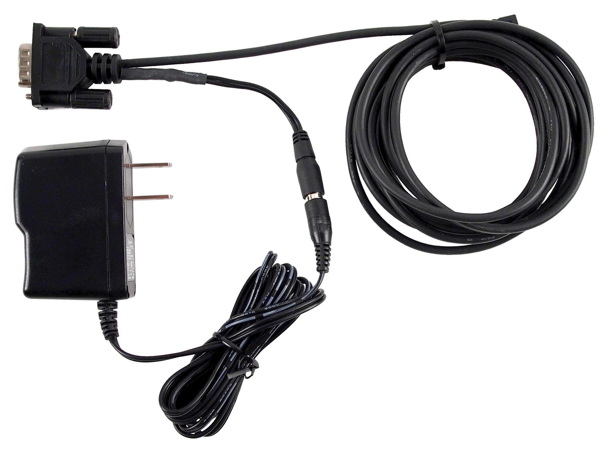
First you will need  6-81499 LCS DB9 CABLE WITH POWER SUPPLY.  Unfortunately these are getting hard to find but not impossible.    This creates the PDI buss for the sensor track and SER2.

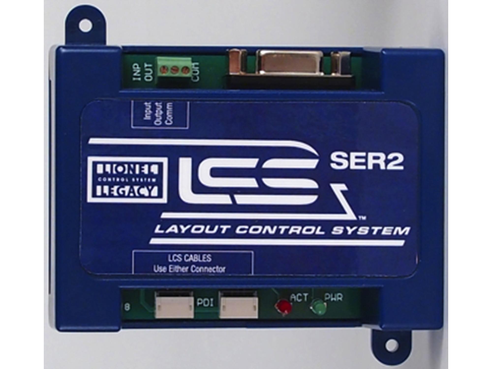
Second you will need a 6-81326 LCS SERIAL CONVERTER 2 (SER2)

The PDI buss plugs into either the Sensor Track first or preferably the SER2 first and then loops to the other.  The SER2 serial out will connect to your ASC. 

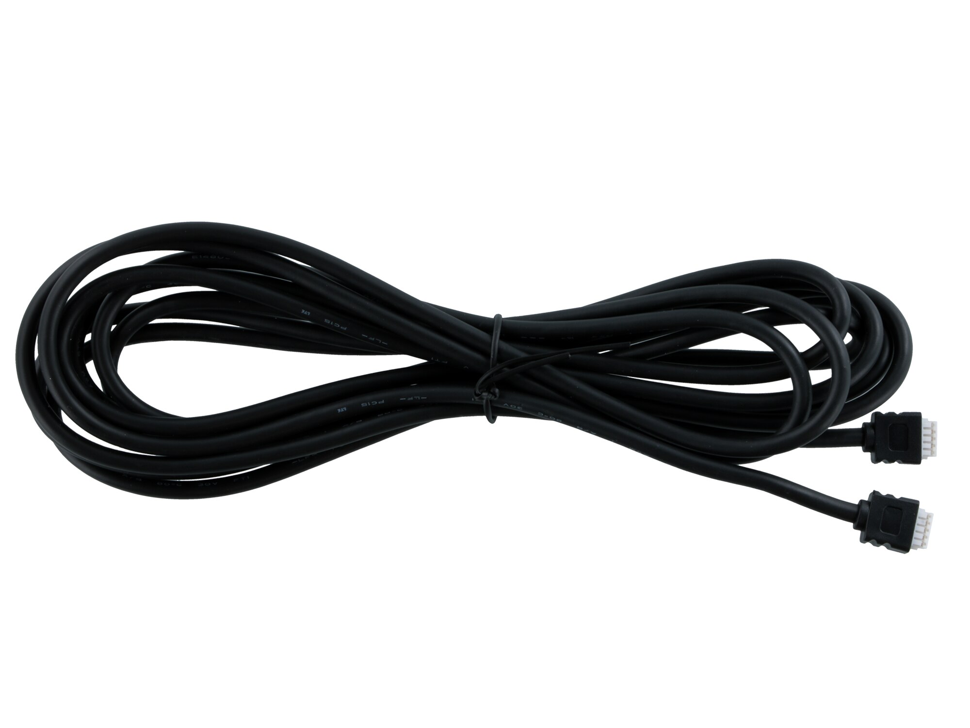
Third you will need a PDI cable to loop the Sensor Track to the SER2.  6-81502 LCS PDI 10FT CABLE.  This is the 10' part number but they come in 1', 3', 10', and 20' lengths.

Here is an older diagram but it works.  Your ASC (not ASC2) would take the place of the TPCs in this diagram.

Marty, I looked at the Serial 2 manual. I have the LCS DB9 and power supply.

I will connect it to a Serial 2 PDI connector.

I will connect the other end of the DB9 to the Legacy Y cable.

I will have to disconnect my old DB9 (that went to my ASC) from the Y cable so I can connect the new DB9.

From the Serial 2 I will use the other PDI connector to connect to my Sensor Track.

From the Serial 2 I will connect the OUT and COM to the first ASC DAT and COM.

Question: Do I leave the power input to my first ASC still connected to a power supply and keep the daisy chains to my next ASC?

Thank you for your help.

@Jeff2035 posted:

Marty, I looked at the Serial 2 manual. I have the LCS DB9 and power supply.

I will connect it to a Serial 2 PDI connector. YES

I will connect the other end of the DB9 to the Legacy Y cable. I assume you are using this to connect to an older TMCC base so old CAB1 remotes can be used?


I will have to disconnect my old DB9 (that went to my ASC) from the Y cable so I can connect the new DB9. YES

LCS SER2 manual https://www.lionelsupport.com/...50SER2UsersGuide.pdf

From the Serial 2 I will use the other PDI connector to connect to my Sensor Track. YES

From the Serial 2 I will connect the OUT and COM to the first ASC DAT and COM. YES

Question: Do I leave the power input to my first ASC still connected to a power supply and keep the daisy chains to my next ASC? Yes, because the ASCs require AC power input completely separate from the data. EDIT- while the above diagram does not show the required external power wiring for the older TMCC style modules- that still has to happen.

Thank you for your help.

Lionel wanted to make LCS blue boxes easier than the previous versions of TMCC boxes (black and grey).

The PDI cable system and matching power supply system provides 12V DC for the logic in the LCS blue box modules. Again, the blue boxes use this PDI cable system, that both carries the power to power the module, and the signal to control it, and they all daisy chain using more PDI cables.

The old grey and black TMCC control boxes (ASCs, AMCs, ARC, etc...) needed an AC aux power input for the logic and separately wired serial data lines for signal- along with yet another power source for the actual accessory they are running. Again, these are all manually wired, and while in theory that wiring can be daisy chained, it's just more work on the part of the user to set all this up.

ARC Daisy Chain Diagram

Also, a related topic if you are using the older ASC devices- a little tidbit of choosing the right device type when setting them up in the app is found in this topic https://ogrforum.com/...al-converter-6-81326

Attachments

Images (3)
  • mceclip1
  • mceclip2
  • mceclip3
Last edited by Vernon Barry

Does not work.

I connected as diagrammed, but the Ser 2 red led stays on, which the instructions say indicate a  problem with PDI cabling or command base.

My command base is the TMCC connected to the legacy (using y cable) to the power supply with the DB9 cable. When I connect the PDI to the Ser 2 I get the constant red light.

My cab 1 and cab 2 run my locos fine. When I press commands the correct lights on the legacy base blink as they should.

How do I trouble shoot?

thank you, Jeff

@Jeff2035 posted:

Does not work.

I connected as diagrammed, but the Ser 2 red led stays on, which the instructions say indicate a  problem with PDI cabling or command base.

My command base is the TMCC connected to the legacy (using y cable) to the power supply with the DB9 cable. When I connect the PDI to the Ser 2 I get the constant red light.

My cab 1 and cab 2 run my locos fine. When I press commands the correct lights on the legacy base blink as they should.

How do I trouble shoot?

thank you, Jeff

So, omit the Y cable just for a moment, PDI starter cable with power supply directly into the base, and then only to the SER- with nothing else attached to the serial 2.

Basic process of elimination- eliminate the "extra" parts- testing if a the bare SER2 and your base can function correctly.

Last edited by Vernon Barry
@Jeff2035 posted:

Does not work.

I connected as diagrammed, but the Ser 2 red led stays on, which the instructions say indicate a  problem with PDI cabling or command base.

My command base is the TMCC connected to the legacy (using y cable) to the power supply with the DB9 cable. When I connect the PDI to the Ser 2 I get the constant red light.

Additional points from the manual https://www.lionelsupport.com/...50SER2UsersGuide.pdf

Edit- "base/no base" is the Wifi unit.

Also note If using a Legacy command base, it must have software rev 1.52 or higher installed.

Operation of LEDs
On power up, the Red LED on your SER2 will turn on for 1 second. If it remains on continuously, this indicates a problem with the PDI cabling or your command base. During operation, the Green LED flickers when commands are passing through the serial input and output of the SER2. During operation, the Red LED flickers when commands are passing through the LCS PDI bus.

Last edited by Vernon Barry

Hi Vernon, thank you.

I did remove the y cable and plugged in the PDI starter cable into the Legacy base and the PDI into the Ser.

Ser Red light on constantly, as before, and no green light on, ever, as before.

When I do commands through the Cab 2 the lights do flash on the base. No green flashing lights on the Ser. Also, I can run my locos fine and accessories programmed as engines work fine.

Do you think the problem is either the command base, or the Ser, or the PDI starter cable? How do I test these?

I do have a sensor track that I have not installed. I hope to do that in a few days. Once installed, I could run the PDI from the starter cable to the sensor track, and the starter cable plugged in to the Legacy base. If it works that would indicate the Ser is defective? And, if it does not work, it will indicate the problem is most likely the Legacy base or the PDI starter cable? Also, have you heard of anyone having problems with the Ser, starter cable, or Legacy output?

thank you, Jeff

Just performed some testing to attempt to simulate an older firmware version on the Legacy base (pre 1.52).

Now, I did not want to attempt to flash very old firmware to my base, but I did have both a Base1L (Blue) and older original TMCC base.

If you just have the PDI power cable and the SER2 plugged in- all by itself, you get the red solid LED on the SER2.

If you plug the 9 pin serial portion of the cable into a proper firmware version Legacy base, you can see the LED blink a fast communication sequence when first plugged in, and then go out- followed by a steady blink of the RED activity LED on the base.

If you unplug the PDI 9 pin serial from the base, the red LED on the SER2 goes back solid.

If you then plug it into an older TMCC base, the RED LED remains lit on the SER2, however, the red activity LED on the TMCC base blinks a steady 1 second flash rate- meaning the SER2 is attempting to communicate with the base, the cabling is working, and the base sees that status check "command" but since the firmware is so old and doesn't support this handshake- the SER2 is not getting the expected response.

Again, I would first check and know what your current 990 Legacy set, Base and Remote, what their firmware versions are. If they don't have the latest firmware and are below version 1.52 on the base- then it may not know to send the handshake to the SER2.

https://www.lionelsupport.com/legacy-control-software

Legacy update video https://www.youtube.com/watch?v=gWuBnt-afNc

https://www.youtube.com/watch?v=OqkVUcQq51I

Again, you should be able to check the function of the PDI power and serial cable using your TMCC base. The SER2 LED won't go out, but the base will indicate it is getting serial commands from the SER2 at about every second a quick flash of the red LED on the base.

Hi Vernon, I have cab version 1.72 and base version 1.60.

With just the pdi power cable plugged in and ser 2 plugged in, I do get the solid red LED on the ser 2.

With 9 pin serial portion of cable plugged in to Legacy base, there is no LED blink on the Legacy base. The red LED on the ser 2 remains solid red. When I unplug the 9 pin serial from the base, the red LED on the ser 2 remains solid, as it always had.

When I plug into the TMCC base, the red LED on the ser 2 remains solid. The red activity LED on the TMCC base DOES blink a steady one second flash rate.

Does this indicate a problem with the Legacy base?

I can run trains fine with either my cab 1 or cab 2.

Vernon, Thank you very much.

I had sent my Legacy 990 system in for a minor tweak on my Cab 2.

I included the base in the shipment to Lionel, explaining I had done exhaustive tests (as you recommended, above) and I thought the problem might be with the base.

They repaired the base unit (I did not know anything was wrong with it); they replaced two boards.

I understand they are no longer repairing the base units, but I guess they had the available parts to do it.

After I got the system back, I connected it to my layout and the sensor track lit up just as you said it was supposed to.

It works perfectly.

Thank you for your guidance and patience in diagnosing my system.

Add Reply

Post
×
×
×
×
Link copied to your clipboard.
×
×