I’m about to start laying track on the layout and definitely NOT good with the wiring scheme / electrical stuff.  Basically, the layout will be Atlas O track with a combo of Atlas O and RCS turnouts.  Step 1 will be laying “sea level” double main lines (approx 70 - 80’ each), with the inner loop connecting to the yard.  Step 2 will be a double or tripleNew Yorkstyle EL line (approx 30 -40’ each), completely independent of all other track.  Step 3 will be a single upper / mountain loop (approx. 70 feet) that will connect to the sea level outer main line.  Overall layout dimensions are 14 x 33.’  All 4 loops will be connected to one Z-4000 and DCS (and likely Legacy soon).  In accordance with MTH and Barry’s recommendations, I plan on Star Pattern wiring it and having track blocks.  


Need help with the following:


1 - I want the ability to independently power down all loops and the yard so I don’t keep electrifying stuff not being used.  As a practical matter, the two mains would both either be on/off at same time.  Ideally, would like the ability to power down mains but keep yard electrified (for playing solitaire).  You’ll note in my schematic that I have assumed toggles AFTER the DCS unit, but perhaps the toggles should be between the Z-4000 and the DCS?


2 – You’ll note that I have a DPDT toggle for the inner main to allow me to power down the inner main but keep power to yard.  But, this still doesn’t allow me to ever turn both off when the Z-4000 is powered up (I came up with an alternate, where I had one toggle coming from DCS and then another toggle immediately after the terminal block that connects to all lines except the yard line – but this seems incredibly complicated).  


3 - I may be overly complicating things with having a toggle to each of the mains, as they will both either be on or off.  But I did this on the assumption that this is probably “cleaner,” because each main would be powered by a separate DCS channel and would be carrying the DCS signal to different terminal blocks going to different loops.  But have no idea if this “separation” is necessary?


2 – Would I use SPST toggles for everything other than the inner loop/yard? 


3 – Just confirming that I should wire all turnouts for each loop to a loop-specific separate power source?  So, I’d have one power source for turnouts, lights and accessories for Main #1 (and maybe #2?), another for the EL and another for the upper line (or one to cover both of these?)? 


4 - I want to put the toggles and the terminal blocks right on the control panel.  Recommendations would be most appreciated. 


Given this is my first time ever trying to plot something like this, my proposed set-up is probably overly complicated and can be done more easily and efficiently.  Please take a look at my schematic and questions above as I would REALLY appreciate your help on all these things.  And, given I'm a total novice, if anyone out there wants to tool around with this schematic and offer the "correct" one (what it SHOULD look like), I would be forever grateful!


Thanks VERY much. 


Peter

IMG_0941[1]

Attachments

Images (1)
  • IMG_0941[1]
Last edited by PJB
Original Post

Replies sorted oldest to newest

Peter,

1 - I want the ability to independently power down all loops and the yard so I don’t keep electrifying stuff not being used.  As a practical matter, the two mains would both either be on/off at same time.  Ideally, would like the ability to power down mains but keep yard electrified (for playing solitaire).  You’ll note in my schematic that I have assumed toggles AFTER the DCS unit, but perhaps the toggles should be between the Z-4000 and the DCS?

If you place the toggles after the TIU outputs, then each time that you power up before turning on the toggle switch for a TIU channel, all of your PS2/PS3 engines will miss the watchdog signal and come up in conventional mode.

2 – You’ll note that I have a DPDT toggle for the inner main to allow me to power down the inner main but keep power to yard.  But, this still doesn’t allow me to ever turn both off when the Z-4000 is powered up (I came up with an alternate, where I had one toggle coming from DCS and then another toggle immediately after the terminal block that connects to all lines except the yard line – but this seems incredibly complicated). 

The yard power is problematical. It's never a good idea to split the DCS signal twice, however, in this case you may have to do so. Have the Inner MAin/Yard power split at the output of the channel into two tangles. One goes on to the terminal block and the other to the yard.

3 - I may be overly complicating things with having a toggle to each of the mains, as they will both either be on or off.  But I did this on the assumption that this is probably “cleaner,” because each main would be powered by a separate DCS channel and would be carrying the DCS signal to different terminal blocks going to different loops.  But have no idea if this “separation” is necessary? 

If it weren't for the Yard split from the Inner Main, you could just use one Z4K handle for both mains and avoid toggles for the Mains altogether.

2 – Would I use SPST toggles for everything other than the inner loop/yard?

You could.

3 – Just confirming that I should wire all turnouts for each loop to a loop-specific separate power source?  So, I’d have one power source for turnouts, lights and accessories for Main #1 (and maybe #2?), another for the EL and another for the upper line (or one to cover both of these?)? 

Thats not necessary, since turnouts throw sequentially, not all at once.

4 - I want to put the toggles and the terminal blocks right on the control panel.  Recommendations would be most appreciated.

Terminal blocks take up a lot of room. They're best placed under the layout.

Barry,


Looks like you're the only one to offer help - thanks very much!


OK - toggles go between Z4000 and TIU - got it.


In terms of a creative way to solve the yard situation, I'm amazed there isn't some way to do this.  So many people have storage staging tracks, etc. that are powered down when not in use.  Must be some way?  Basically, it sounds like my only option is to have a DPDT toggle on the inner main and have this main line powered up even if I just want to operate in the yard.   


Regarding separate power sources for turnouts and accessories, was thinknig that I don't want to be powering a turnout on a track not in use, as this could be electrifying a loco sitting on that track.  Am I over-thinking this? (please don't respond with just a "yes," at least let me understand why. lol).


Just to confirm - I plan to use 14 gauge paired wires to each block (- I experimented with by putting one 18 gauge pair at one end of one long length of track and a 14 gauge pair on another long length and was amazed at how much further the loco on the 14 gauge track ran - so power flow is clearly much better).  BUT - my wire runs for one block will NOT be anywhere near the same length as my wire runs to another block on the same track loop.  In fact, one wire run on a particular loop can be 2 feet long while another on that same loop could be 25 feet long.  This will "not" be a problem for DCS because the specific pair of red/black wires to any particular block will - themselves - be virtually the same length even though that pair will be drastically different in length than other wires running to other track blocks on that same loop?


Thanks again,


Peter

Peter,


What you post is essentially correct. However, as regards toggle switches, I wire my layout a bit differently.


I have 6 power districts on the layout, each with associated yards and/or sidings, and each power district is controlled by one Z4000 handle with a Z4000 Remote Commander for a total of 6 Z4K Tracks.


I have all of my power districts un-toggle switched and use a separate toggle (SPST) on each individual siding. However, I have no need to have mainlines unpowered while yards and sidings associated with that mainline are powered. (I don't understand your earlier reference to "solitaire")


This is a bit more work, however, it gives me a great deal of flexibility as regards keeping some engines unpowered and only powering the ones I want to operate, when I want to operate them.


Hi Peter,

Sounds like you already got the right ideas and a good plan.  I was reading your post and I had the very same thoughts about the separate loops and toggles (before I started my layout). I'm not that knowledgeable with the DCS but can attempt to explain how the loops were wired on our layout. I'm going to buy Barry's book this weekend. 


My layout is small compared to what you're going for.  Even so, we did separate the three power districts with separate power sources, one from each side of the Z4k and one from a Z750.  I push them up to about 18v before I move the trains.


Each of the (3) power districts were seperated with a toggle switch.  Under normal DCS operating conditions the toggle switches are open.  


What really helped me digest the wiring concept and keep things straight was to pick a color for the different track loop and all associated wires right from the transformer to the TIU and then out to the rails.  By color coding the wire and loop it allowed me to go from two toggles (separating the three loops) to taking it a step further and installing blocks in each of the power districts - I'm so glad I did too.


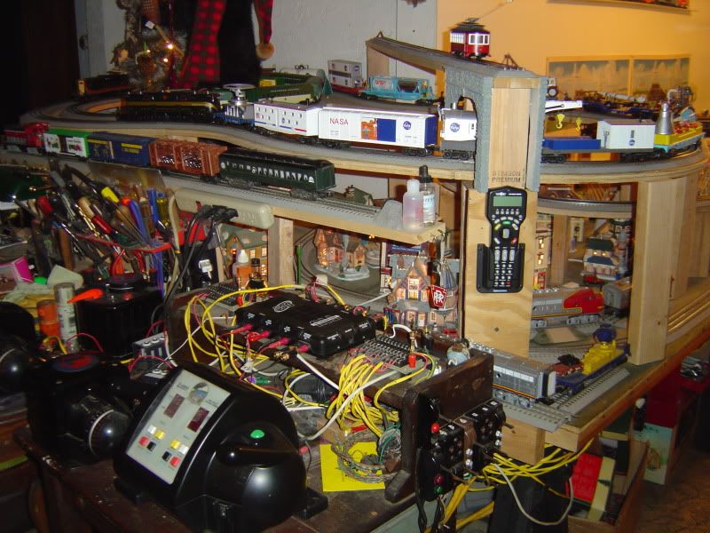
Here is a picture of the color coded loops, the toggle on left and right on my mini control panel separates the three transformer sources.  Red District, Green District and (upper mountain) Orange district. 


Cant take any credit for the wiring, had an awesome and patient conductor (Dewey) guiding from the beginning.


Last edited by litegide

Barry – first, thanks once again for taking the time to help a novice, and offering such timely advice.  You’ve probably been asked these same questions 1,000 times, yet you have the patience to keep helping newbies like me.  Thanks!  


Barry - you may recall that I had posted many months ago after watching the OGR DVD about DCS.  The reason for my post then was that the DVD gave me the impression that my “simple” layout was going to require power districts, with multiple power sources and TIUs.  But you advised against power districts in my case, as “overkill” due to the lower power demands of today’s trains.  Your advice, however, was based on my old layout plan, which was 14x19 with the same basic lines (double mains, a triple EL line and a mountain pass line).  With my expanded layout plan, would that advice still hold true or are you suggesting that I might want to look at creating power districts?  Would prefer not to have power districts if possible due to the extra cost and complication.  But, would rather know now and plan accordingly.  


Litegide 24  - you control all three power districts through one toggle switch?  What type?  And, are you using three TIUs?  Also – thanks very much for the advice and very helpful photo.


Thanks very much,


Peter   

Peter,


The need for power districts is all about what you run and how many amps it consumes, vs. the available power from your power source through the TIU.


Since the TIU can only safely handle about 10 amps per channel, if and only if, you have demands on a channel that exceed 10 amps, you have two choices:

  • You can use a transformer that exceeds 10 amps, or multiple transformers that do so if combined via a Lionel TPC or equivalent device, wired in Passive TIU mode
  • You can implement Power Districts so that more than one transformer/channel services a loop.

Although your layout has grown, as long as you had enough power before without resorting to either of the above techniques, and you're still running trains with the same power requirements, you shouldn't need to implement Power Districts.

Originally Posted by Barry Broskowitz:

Peter,


The need for power districts is all about what you run and how many amps it consumes, vs. the available power from your power source through the TIU.


Since the TIU can only safely handle about 10 amps per channel, if and only if, you have demands on a channel that exceed 10 amps, you have two choices:

  • You can use a transformer that exceeds 10 amps, or multiple transformers that do so if combined via a Lionel TPC or equivalent device, wired in Passive TIU mode
  • You can implement Power Districts so that more than one transformer/channel services a loop.

Although your layout has grown, as long as you had enough power before without resorting to either of the above techniques, and you're still running trains with the same power requirements, you shouldn't need to implement Power Districts.


Yes, you clearly explained that power demands were the driver on whether power districts are needed.  At the time, I thought trains drew more juice.  The reason I am asking now is because, with increased loops, I could be running longer trains, or two on one loop.  Currently, we have stuff like the following: N&W J (MTH Premier) steam passenger - with aux. water tender, full vista car and 5-7 passenger cars; or NYC (MTH Premier) Mohawk with 9 heavyweight Madison passenger cars; or the Visionline UP Challenger (if I ever get my hands on one), likely with freight cars.  Maybe at some point, 2 shorter trains on one loop?

Originally Posted by Joe Allen:


IMG_0941[1]


Peter,

I don't know if you realize that the #2 & #3 posts of your Z-4000 transformer diagram above only put out 14 and 10 volts and 3 amps. They are meant for accessories.


I wouldn't use anything smaller than 16 gauge wire. 18 gauge wire may over heat with 10 amps if you get a derailment.


Joe Allen,


Really?!   Well that sucks - I thought there was a way to also make them "fixed" to operate like posts #1 and #4??  Thanks for the heads-up.  Guess I need another power source to run four independent loops no matter what?


Peter


 Guess I need another power source to run four independent loops no matter what?

  Maybe not, It would depend on how many trains you will have powered  up if you used one Z-4000 handle for 2 channels.. There's nothing wrong with using one transformer handle to power 2 TIU channels . Just jumper the input side.


Originally Posted by PJB:


Joe Allen,


Really?!   Well that sucks - I thought there was a way to also make them "fixed" to operate like posts #1 and #4??  Thanks for the heads-up.  Guess I need another power source to run four independent loops no matter what?


Peter


Peter,

The accessory posts are Fixed (center) and the handles (outer) are Variable on the Z-4000.


When talking about Fixed, we are referring to the channels of the TIU, not the transformer. The TIU has 2 Variable channels and 2 Fixed and the Variable channels can be set to Fixed so that they operate the same as the other 2.


This way whatever voltage is applied to the inputs is passed though the outputs. If you are running all command engines or using Z4K tracks, this is the way to go. It saves a few steps each time you power up to operate.

Peter;

Further to what Gregg said, each handle of a Z-4000 puts out up to 10 amps.

Modern engines don't draw much more than 2 amps or so, depending of course on loading, even with a smoke unit running.

So you can run several trains at once with each handle siamesed to supply two TIU channel inputs. This will allow you to operate several hundred feet of track with one Z-4000 and one TIU.

If you are running passenger cars with conventional lighting, this will of course reduce the number of trains you can run.

You could always start with one Z-4000 wired as above, then add a second when needed.


Rod

Litegide24 - thanks very much for posting the photos. Very helpful but as a first timer, the complexity of all that wiring is basically scaring the **** out of me.


Errata - I had created my wiring schematic a while ago and generically put "Z4000" for the power, not bothering (for purposes of wiring scheme) to worry about whether this was actually going to be comprised of one or more power sources. In the interim I forgot and got it into my head that a Z4K had 4 posts, each capable of powering a loop. As it stands, I think I'm all set with toggles. With 2 Z4Ks, I would only need one - for the inner main that connects to the yard. Each other loop will have it's own handle. Even with this "snafu" all the the inputs have been tremendously helpful, and I know I now have a much better handle (no pun intended) on the wiring - thanks very, very much.


One question though - if I have one power source powering outer loop that connects to upper loop, and another power source for the upper loop, don't I somehow need to ensure the voltage or watts (or whatever) is identical for both these two loops so that a train traversing from the outer main through the switch and onto the upper isn't getting two different voltages?


Thanks again


Peter

Last edited by PJB

Gentlemen,

  If more power is required, which I doubt at this point, instead of another Z4K he could invest in a pre war ZW, or two.  They are a great power sourse and a lot less expensive than another Z4K and run the DCS quite well also.  Further they also can handle all the switches he will ever run. 

PCRR/Dave


We actually had 1 Z4K, 2 ZW's and 1 KW powering our 5 level layout and it cost less to pick up the 1 ZW and 1 KW than to purchase another Z4K.  Remember if you use the ZW or KW transformers you must invest in 10 Amp Breakers or quick blowing fuses to protect the DCS TIU.


Last edited by Pine Creek Railroad
 

One question though - if I have one power source powering outer loop that connects to upper loop, and another power source for the upper loop, don't I somehow need to ensure the voltage or watts (or whatever) is identical for both these two loops so that a train traversing from the outer main through the switch and onto the upper isn't getting two different voltages?


Thanks again


Peter


I never had any fluctuation of speed going from one loop to another (or crossing over toggle switch).  My district separation toggles are left in open position.


On the z4k handles I power the display voltage to about 18v for each side.  My upper mountain loop is run by a z750 (with dial positioned set at approx 18v), don't have a voltmeter on that loop but have a k-line boxcar (with a voltmeter built in).  


I think an important thing to consider was that if using multiple transformers that they are phased alike and the common bus can be shared over all loops (or districts).  The experts can chime in here but from what I remember there was a safety rule though, ie; if one transformer were left unplugged power could backfeed through windings in other transformer and potentially cause electrical shock hazard at the male end of the plug.


Post
The DCS Forum is sponsored by
×
×
×
×
Link copied to your clipboard.
×
×