I've been following this subject for a couple of months now and I believe I have all the correct

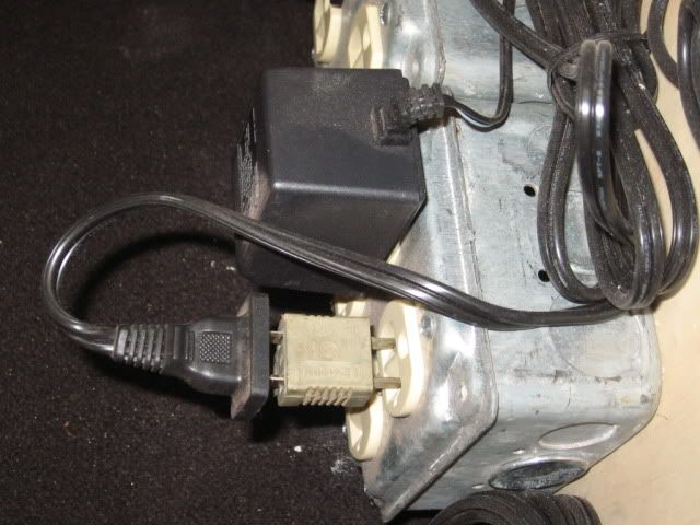
information accumulated from all the Forum questions and answers. I can use four 180 Watt Powerhouse power supplies to power the TIU by connecting a 6-14194, TPC cable to each powerhouse connector.  Then, using banana plugs, with the hot being the center pin and the neutral the bottom pin, I can plug into either the variable or fixed channels after the TIU is set up with "all channels fixed" and the TIU set on "super" for multi TIU operations.  For circuit protection the 180 watt powerhouse breaker is completely reliable and quick.  On the output side I connect the commons together.  I'm surprised that the Lionel You Tube site hasn't covered this subject as it is the Lionel power supplying the power for the TIU.  I have the reverse polarity plugs in place as all my powerhouses were part of batch "2000  46" that had an internal reverse polarity problem. Each powerhouse will put out 18V at 10 amps. Also, if I have a TIU powered by two throttles of a Z4000 going into either two of the fixed or variable input channels, I can supplement with the powerhouse power supplies to act as additional power for the other two channels.  The only other thing I would need is a voltmeter for each powerhouse to monitor the voltage out of the TIU for each channel.  


Moke Mike


lineswest@hotmail.com

Original Post

Replies sorted oldest to newest

Originally Posted by RJR:

I don't know why you'd need output voltmeters if you have all channels set to fixed, since the output voltage woulkd approximate the input voltage.


I don't know how many trains you plan to run, but 180 watts should be able to power more than one TIU channel.

Thanks for your reply.  I'm running multiple trains with multiple lash-ups and when running TMCC engine/s, voltage is drawn down, whereas using only DCS engines in Proto 2 or 3, voltage is rarely drawn down.  Yes amperage goes up on either type of engine.  What I'm trying to determine, with the voltmeters is to see how much voltage I'm loosing on a particular block and then follow the train around the 180' foot track and see if it will draw down more than I'd like to see,  I bought four, 3rd Rail E-7's and when lashing them up in two pairs, each pair takes nearly 6 amps and draws the Z4000 transformer down to 16 volts from an original preset of 19 volts.  On a Z4000 transformer you can nudge the throttle back up to 18 volts and the E-7's will regain their speed.  With 180 W powerhouses, you can't nudge up from 18 volts.  That's all there is.  The 180 W powerhouses have a 10 amp capability, however; the 18 volts output is a starting voltage without the E-7's using a hefty 6 amps.  The voltmeters  will let me know if the voltage has been drawn down and if it's significant enough to 

affect the speed of the E-7's.  If it is, I can't do anything about it except removing  the E-7's and installing them on a Z4000 and TIU loop.  Then I'll use the 180 W powerhouses and TIU to run DCS engines only.


You mentioned that the 180 watts should be able to power more than one TIU channel.  The DCS O Gauge Companion states to use one Z4000 throttle for each TIU channel.  Since the 180 W powerhouse is nearly identical in voltage and amperage out put, I was going to use one 180 W brick per channel, and set the 180' of track up into power blocks.   Can you split the 180 W powerhouse into two channels be adding 

multiple pigtails and banana plugs at the end of each 6-14194 cable set and then plugging into two TIU channels?


Thanks for your input.  mokemike


I power my track with a 180 brick and I use both DCS and Legacy. I often am running 2 MTH engines and 5 Legacy engines at the sametime, most of them with smokE and have no problem. I do have another 180 in parellel hooked up but rarely do I need to have both on. I am not an expert by any means but it works for me. I would listen well to the other posts.  

Originally Posted by Gilly@N&W:

If you're asking for a source of Voltmeter, here's the one I bought from LightObject.com

They are very affordable and there is a matching ammeter as well if you're interested.


Thanks for the voltmeter and amp meter info.  I went to their web site and found them almost right away.


mokemike

Originally Posted by Jeff Metz:

I power my track with a 180 brick and I use both DCS and Legacy. I often am running 2 MTH engines and 5 Legacy engines at the sametime, most of them with smokE and have no problem. I do have another 180 in parellel hooked up but rarely do I need to have both on. I am not an expert by any means but it works for me. I would listen well to the other posts.  

Thank you for your comments.  I am puzzled by your outstanding power performance.

Approximately, how many feet of track are you powering?  Are you only using one 180 watt powerhouse supply to operate one TIU and all four channels?  When you use two 180 W powerhouses, in parallel, that doubles the output, do you use that power to power all 4 channels of the TIU?  


I don't want to waste the energy of 180 W powerhouses by applying them in an overkill when fewer powerhouses would accomplish the same desired results.  I have 4, 180 W powerhouses.  Each puts out almost the same voltage as one Z4000 throttle.


I have powered all four channels of a TIU with one Z4000 for about 200' of track and with block division, it proved satisfactory to successfully power two lash-ups of two DCS engines each, as long as neither were on the same block at the same time.  Four engines on TIU channel at the same time will usually trip the Z4000 breaker as each lash-up is pulling at least 20 cars each.  When this happens, I never have a voltage drop on the Z4000 meters, however, i definitely can see the amperage getting too high.


A MTH DCS lash-up will usually draw about 4.5 amps and have no affect on the 19 Volt preset.  A second MTH DCS lash-up will have the same results without a problem. However, two 3rd Rail E-7 lash-ups, each only having a single inefficient can motor, will draw 6 amps per lash-up and draw the Z4000 voltage down to 16 volts with a subsequent loss of available speed for each lash-up.


I'm using 12 and 14 gauge wires for the nearly 200' of track with all four channels of one TIU in use.  With the Z4000, I can readjust the throttle on each side of the Z4000 to 18 volts to regain speed.  Amperage become an area that needs to be monitored, unlike Lionel, Atlas, K-Line, Weaver TMCC engines compared to the 3rd Rail lash-ups.  Also, MTH DCS lash-ups do not required monitoring either as they don't draw enough amperage or voltage to affect their performance or speed.  Using 180 W powerhouses does not allow for bumping up the voltage to regain the speed on the two lash-ups as you can't bump up without a throttle.  If 3 powerhouses will perform the task, instead of all 4, I'm certainly open to any of your suggestions and please tell me as much about the amount of track and sidings your have for your operation.


Thanks so much.


mokemike 

Just curious, if you have to adjust the Z4000 handles for a heavier load, wouldn't it be just as easy to adjust the throttle on the locomotive?  Also, I'm curious about your statement that the locomotives slow down.  Are these locomotives without cruise capability?  I just tested one of my Legacy locomotives and an MTH PS2 running through one fixed TIU channel.  I can vary the input voltage (using a KW) from 12 volts to 20 volts, and as near as I can tell, no speed changes.


I normally run with a pair of 180 powerhouse supplies, two channels on each one.

My experience with voltage is the same as Gunnerjohn's.  Locos seem to operate as low as 12 volts, although the loud chuff cuts in sooner.  I suggest that instead of measuring the voltage at the TIU, you take a voltmeter and check voltages when & where a heavy train is running.  You may be surprised at the voltage loss in track, for which the cure is more insulated blocks and heavier gauge feeds.  With the loads you have even 12-gauge might be called for.


WARNING:  If you have 2 transformers with outputs wired in parallel, if you unplug one of them, the prongs on that plug will be about 120 volts even though that transformer is not connected to the house line.  It will be back fed, its secondary wionding becoming a primary winding so that it functions as a step up transformer.  If they are variable transformers, like the old ZW's, you can get over 240 volts. 


Using DCS, you wouldn't want to feed the output of paralleled bricks through the TIU.


 I have 4, 180 W powerhouses.  Each puts out almost the same voltage as one Z4000 throttle.


Mike, the voltage isn't the determining factor.  My 1941 Type R 100-watt will put out 24 volts.  What is important is the wattage, which is tied to the gauge of the internal wiring and therefore to the amperage that can be pulled. 


If you are using the Z4k controller & the fixed channels, the Z4000 voltmeters stay rock steady, because they do not reflect the actual output voltage but somehow relfect the setting imposed by the controller.  I'll defer to the MTH techs & the gentleman from Lake Forest to discuss that one.. 

The way I see it you may want to measure the other end of the equation. It really doesn't matter as much what is coming out as what the engines are seeing. Unless you are pulling too many Amps of course. I used to use my PS 2 locos to take voltage readings at different locations around the layout, but I noticed a varriation between engines so I now I just use a Multimeter. For instance our new PS3 Railking Dash8 is convinced that there are 26v on the track, but the Multimeter shows 16v-18v.


Just FYI, 14 gauge is usually good for 15A and 12 gauge up to 20A.

Originally Posted by Barry Broskowitz:

Gentlemen,


FYI, if several PS2 engines draw down the available power, each engine will compensate by decreasing its available top speed. Any engine that is traveling faster than its new reduced top speed when the power demand decreases that top speed will slow down.

Interesting, I did a further test with the PS2 locomotive.  I have it running at a scale 10 MPH and varying the voltage from 12 to 20 really didn't vary the speed.  It would cover the same distance at either setting. 


Is the locomotive reducing the maximum speed possible or changing the meaning of the scale MPH reading?  It seems the voltage doesn't affect it in slow running in any measurable manner.

John,

Is the locomotive reducing the maximum speed possible or changing the meaning of the scale MPH reading?

As I said, it's reducing the maximum speed.

  It seems the voltage doesn't affect it in slow running in any measurable manner.

Again, it won't have any effect at low speeds below the reduced maximum speed.


As an experiment several years ago, I once set my Z4000 to 18 volts and ran 3 trains with PS2 engines on a single loop:

  • A steamer with 3 lighted passenger cars.
  • A diesel with 5 lighted passenger cars.
  • A 2-diesel lashup with a lighted caboose.

Al of the engines had smoke on. As I increased speed, all of the engines topped out at about 50 SMPH or so.

Originally Posted by gunrunnerjohn:

Just curious, if you have to adjust the Z4000 handles for a heavier load, wouldn't it be just as easy to adjust the throttle on the locomotive?  Also, I'm curious about your statement that the locomotives slow down.  Are these locomotives without cruise capability?  I just tested one of my Legacy locomotives and an MTH PS2 running through one fixed TIU channel.  I can vary the input voltage (using a KW) from 12 volts to 20 volts, and as near as I can tell, no speed changes.


I normally run with a pair of 180 powerhouse supplies, two channels on each one.

Hello.  I'm not sure what you mean by adjusting the throttle of the locomotives.  I've always considered the transformer throttle, "the locomotove throttle" as it controls the speed of the engines.  If I preset the Z4000 throttle at 20V, I know that when the 

two sets of E-7's begin to run, even without cars, that the voltage will drop to about 17V.  If I preset the Z4000 throttle at 18V, the indicated voltage will drop to 16V and when I'm at 16V and move the throttle back up to 18V, the two E-7's will increase their speed rather visibly.  Once I've adjusted for the E-7's voltage load, everything stays at the new voltage of 18V.  These engines are 3rd Rail.  They do not have Legacy, however, they are equipped with Electric Railroad (ERR) cruise control. Since both engines are independent of one another without a tether cable as K-Line used to use, each engine has it's own idiosyncrasies, just as two identical Lionel TMCC engines often have when you do a lash up.  They are close, but not the same. If I leave the E-7's out of cruise in TMCC, they tend not to fight one another as much. 


Going around a single loop of track nearly 200' long causes a TMCC engine to vary speeds as it encounters different signal strengths due to all sort of reasons.  Distance from command base, metal objects close to the track, engine moves out of line of sight with command base, engine passes another train on an adjacent siding and reacts either to the metal cars or engines at the head of the train, actual track voltage at different locations, etc,.  Since all outside rails are connected to one another and a ground plain was installed between the two cork halfs of the road bed, I get a very good signal on the newer Lionel and Atlas TMCC engines.  Engines older than 10 years, either work or they don't.  Adding another ground plane next to the track area that the engine/s want to stall on, helps significantly too.  Regardless, the two engines and their individual R2LC board will dictate their performance.  After changing out the R2LC's about 4 times for each engine, I finally got both to run as a pair in a TMCC lash-up.  However, when I used the Cab 1, to command them into ERR cruise, they reacted so much separately from one another, I was forced to go back to no cruise.  These 3rd Rail engines are the first that 3rd Rail has released in a diesel configuration and there are things that were not anticipated by Scott at 3rd Rail that will cause his second run of E-7's to have a different final configuration.  However, I'm stuck with what I got as the new E-7s will also have only one can motor, at the present gear ratio and amperage draw, using a rubber belt drive.


Thanks for your input about using two 180W powerhouses to power the TIU.  Since I first posted I was going to use 4 powerhouses, the trend on all of the reply have been saying the same thing as you have said.  I don't need to use four !80W powerhouses for one TIU. 


Please tell me what yoo were referring to when you stated that I should use the locomotive's throttle?

Originally Posted by RJR:

My experience with voltage is the same as Gunnerjohn's.  Locos seem to operate as low as 12 volts, although the loud chuff cuts in sooner.  I suggest that instead of measuring the voltage at the TIU, you take a voltmeter and check voltages when & where a heavy train is running.  You may be surprised at the voltage loss in track, for which the cure is more insulated blocks and heavier gauge feeds.  With the loads you have even 12-gauge might be called for.


WARNING:  If you have 2 transformers with outputs wired in parallel, if you unplug one of them, the prongs on that plug will be about 120 volts even though that transformer is not connected to the house line.  It will be back fed, its secondary wionding becoming a primary winding so that it functions as a step up transformer.  If they are variable transformers, like the old ZW's, you can get over 240 volts. 


Using DCS, you wouldn't want to feed the output of paralleled bricks through the TIU.


 I have 4, 180 W powerhouses.  Each puts out almost the same voltage as one Z4000 throttle.


Mike, the voltage isn't the determining factor.  My 1941 Type R 100-watt will put out 24 volts.  What is important is the wattage, which is tied to the gauge of the internal wiring and therefore to the amperage that can be pulled. 


If you are using the Z4k controller & the fixed channels, the Z4000 voltmeters stay rock steady, because they do not reflect the actual output voltage but somehow relfect the setting imposed by the controller.  I'll defer to the MTH techs & the gentleman from Lake Forest to discuss that one.. 

Thanks so much for your input.  I understand what you're saying about voltage or wattage and it's affect on engine performance and speed.  At the output of each 180W powerhouse, I've used a multimeter, and it's digital display of voltage for a starting point of determining the layout's performance.  Then on each power block, I've attached another multimeter for measuring voltage at that track location.  (Sears, Lowe's and Home Depot frequently have decent multimeters at a very reasonable price of under $20 each, at their Christmas sales.) Comparing the two voltmeters for each track block and 180 W powerhouse output gives me nearly identical readings.  I'd be concerned if I saw a difference of more than 1.5 volts as all my comparisons are about 3/4's of a volt.  (Each voltmeter, made by different manufactures, may read different voltages for the same output.  I know that and have used a single steady output to compare all the voltmeters on that single source to determine if any are out of calibration.)


I have been running TMCC and DCS on the same tracks for a long time and read the 

amps and volts on the Z4000's as different engines go from block to block and you can see their travel as the voltmeters and amp meters coincide with the travel over each 30 to 35' of track block and then reaches the next block.  Although the voltage and amperage changes, particularly noticeable on TMCC older engines, the engine will not slow down although the voltmeter has dropped from 19 volts to 16 volts.  The E-7's made by 3rd Rail are the exception.  As they start on their forward speed of an estimated 15 mph, and draw the voltage from 19V to 16V, they slow down noticeably.

Adjusting the throttle back to 18V also cause to E-7 lash-up to noticeably regain their speed and hold it until they reach the next Z4000 power block on a different Z4000.

Then a throttle adjustment back up to 18V allows the engines to regain their former speed.  


this may not be the same as we've all seen with other DCS and TMCC engines, however; it is the performance of these 3rd Rail, first edition, E-7's.  It's not adversely impacting my layout's performance, as long as I know how much voltage and amps I've lost so I can adjust.  The point I was trying to make was that with 180W power houses are not adjustable.  If I have volt and amp meters installed I'll be able to detect and determine if I want to operate the E-7's on 180 W blocks or install a Z4000 which allows voltage changes while the engines are running.  


Just as a test, I put both E-7's into PGM, reversed the lead on the can motor of the trailing E-7 so it wold start in reverse and locked them into conventional forward.  I then installed them on a 200' loop of track controlled by three power blocks, each made up of two 180W power houses and a TPC 400.  The maximum speed of the E-7's was a guess of about 35 mph.  I then installed the same engines in the same configuration on the next loop of track and I powered that one loop of track of 200', with a SINGLE Z4000 throttle.  The estimated speed of the E-7's was near 50 mph. 


That tell's me that although I have 20 amps available at each TPC 400, I can't go any faster as I can't increase the 18V output of each 180 W powerhouse and it's TPC.

If I put a Lionel or Atlas TMCC, set in PRG or a Williams engine, with all the engines in a double head-end, engine configuration, that will run in conventional if separated by about 4' of track to insure they are a matched set, those engines will pull 50 weighted cars at speeds too fast for the curves 138 radius curves.  The Lionel, Atlas and Williams all have voltage thresholds that allow them to run at or near the same speeds with lower voltages than the E-7's can adjust to.


I hope this explanation clarifies the 3rd Rail E-7's dictating a different approach than we've all see with other TMCC and DCS engines and my attempts to integrate them using whatever power will allow the highest speeds while pulling GGD passenger cars.

Originally Posted by Barry Broskowitz:

John,

Is the locomotive reducing the maximum speed possible or changing the meaning of the scale MPH reading?

As I said, it's reducing the maximum speed.

  It seems the voltage doesn't affect it in slow running in any measurable manner.

Again, it won't have any effect at low speeds below the reduced maximum speed.


As an experiment several years ago, I once set my Z4000 to 18 volts and ran 3 trains with PS2 engines on a single loop:

  • A steamer with 3 lighted passenger cars.
  • A diesel with 5 lighted passenger cars.
  • A 2-diesel lashup with a lighted caboose.

Al of the engines had smoke on. As I increased speed, all of the engines topped out at about 50 SMPH or so.

Barry, thanks for filling in with your experience and knowledge that helps all of us to get a little closer to understanding more about our layouts and their requirements to get the most performance whenever possible.


mokemike

BY "adjusting the throttle, I'm talking about the remote Throttle, either the DCS or CAB1/CAB2, depending on what you're running.  We are talking command here, right?


I tried a Legacy and an MTH, and the input voltage to the TIU made no difference at slower speeds.  I got up to around 50 scale MPH, and I actually did my measurements of distance traveled at 10 scale MPH and a like speed with the Legacy.  As pointed out by Barry, maximum speed may suffer, depending on the actual track voltage, I did not test any maximum speeds.


I have also not tried the ERR Cruise Commander or Cruise Commander M engines, that would be another good test.  Since the ERR cruise is based on motor back-EMF, perhaps that behaves a bit different with different voltages, though I've never observed a huge difference with different loads.  I also didn't actually test the track voltage at various points with cruise performance in mind.


For MTH or Legacy engines, I don't see how a couple of volts track voltage would make any measurable difference in the locomotive speed at anything other than the maximum voltage limited speed.  Another interesting test would be one of the TAS EOB equipped locomotives, they also use the tach strip on the motor and should not be seriously affected by voltage differences on the track.


This is a good experiment for ERR Cruise equipped ones, I'll have to give that a look.  That's the type of cruise that I can see the track voltage may have an effect.


This post starts with some anecdotal info regarding my layout power setup... I figured it would help to describe my setup...


I use 180W bricks to power my home layout...  One brick supplies the power to each TIU channel...  All TIU channels are set to fixed mode...  Each channel goes to a MTH terminal block and then out to the track blocks...  I have wired with 16 gauge OGR [and other same type] wire...  I run DCS and TMCC/Legacy 99.44% of the time... I can run conventional using IC/Lionel TPCs which are in series in each channel between the bricks and the TIU inputs...  I installed a bypass switch for each channel so that the TPCs are only active when running conventional...


I have run this way for over 6 years without any power issues...  I always run lashups, especially with PS2/PS3 locomotives...  my layout size is 22X16 with 2 main loops and some other trackage...


How many TIU channels do you use to provide power to your track?  Do you have a Brick connected to each TIU input?  Do you have any way at present to measure the current draw from each TIU channel?  That might tell you if you're getting sufficient current to each track to power your locomotives...


Originally Posted by gunrunnerjohn:

BY "adjusting the throttle, I'm talking about the remote Throttle, either the DCS or CAB1/CAB2, depending on what you're running.  We are talking command here, right?


I tried a Legacy and an MTH, and the input voltage to the TIU made no difference at slower speeds.  I got up to around 50 scale MPH, and I actually did my measurements of distance traveled at 10 scale MPH and a like speed with the Legacy.  As pointed out by Barry, maximum speed may suffer, depending on the actual track voltage, I did not test any maximum speeds.


I have also not tried the ERR Cruise Commander or Cruise Commander M engines, that would be another good test.  Since the ERR cruise is based on motor back-EMF, perhaps that behaves a bit different with different voltages, though I've never observed a huge difference with different loads.  I also didn't actually test the track voltage at various points with cruise performance in mind.


For MTH or Legacy engines, I don't see how a couple of volts track voltage would make any measurable difference in the locomotive speed at anything other than the maximum voltage limited speed.  Another interesting test would be one of the TAS EOB equipped locomotives, they also use the tach strip on the motor and should not be seriously affected by voltage differences on the track.


This is a good experiment for ERR Cruise equipped ones, I'll have to give that a look.  That's the type of cruise that I can see the track voltage may have an effect.


Thanks for the clarification.  The procedure for starting TMCC or DCS engines is to set the voltage first at 18V or 19V on the Z4000, depending on which publication you read.  After setting the start voltage at 19V, and using the Cab 1 to start the engine,

the start up and forward motion of the engine is normal.  However, no matter how many times you turn the big red knob on the Cab 1, the engine won't go faster than about 15 mph.  The engine is not geared for optimal speeds nor is the very high amperage demands of the can motor the optimal choice.


Now that the engine is rolling forward at 15 mph and you've turned the Cab 1 throttle clockwise as many times as you want, you have to physically reach down and return the Z4000 voltage back up to at least 18V, indicated and then the Cab 1 will move that engine lash-up out fast enough to have to slow down for 138 radius curves, as you would any other TMCC engine.


if you don't trim the voltage up from the draw down to 16V, and adjust it back to 18 or 19V, you're going to be running a very slow set of engines with the Cab 1.  This is not a ERR problem, but a first generation ever release of a 3rd Rail diesel engine that isn't up to normal standards for TMCC.  The first issue was a "guess" for gear ratio,

type of can motor, RPM optimal can motor speeds, and all the other things that should have been verified before release of the E-7's.  Once one understands that the voltage has to be set higher, the E-7's will perform correctly.  


When I first ran in to this problem I came to OGR Forum, asking others if they were having any performance speed issues with their new E-7's. The two significant replies I received were "What speed Problem?"   After asking what they were using for power and how many feet of track was being supported and their TIU channel configuration, I realized that they had never fully understood the power requirements of a DCS set up "by the book".  


What they had done was grossly over-powered the layout with double the Z4000 power and TIU power distribution requirements.  Secondly, they had only bought only one E-7, as the RR they were modeling only used one E-7 for prototypical performance.  


Once I understood how they were so satisfied with the speed performance, I bought a second Z4000 and split the layout into two separate Z4000 power distribution zones.

Now that I had far more Z4000 layout power required to operate a normal DCS and TMCC layout, I too, could get the E-7's up to 60 mph.  However, before I added the second Z4000, my entire DCS and TMCC layout performed flawlessly using the star pattern of wiring that I've been using since 2004.  The loop powering the E-7's, prior to installing a second Z4000, was my third expansion of the 2800 sq ft layout and I'd never had a problem before.  Dave Hikel drew my first layout wiring schematics for me and using his diagrams, I wired the entire first section of the layout, placing the TIU's per his diagram and running the four color coded wires to each pickup point and to each TIU in and out channel.  Dave came down from Seattle to my Sacramento location and installed a turn table for me and he then fine tuned the layout as needed.  He also pointed out areas on the layout that needed tweaking to also support TMCC on the same tracks as the DCS.


So on this third layout expansion, it was not only by Barry's book, but also by Dave Hikel's recommendations.    Dave recommended that when laying the cork roadbed, to place a 18 or 20 ga wire down the center of the cork, instead of having to lay the ground plane on the outside edge of the tracks.  For the first time, I could run any TMCC engine flawlessly.  I also had the correct number of track feet between pick ups and the center rail breaks as per the requirements.  And last, but not least, I had the right amount of Z4000 power. Everything worked perfect for DCS and TMCC.


Except for running a 3rd Rail E-7 lash-up in TMCC.  (Lessons learned.)


mokemike


Originally Posted by JimQ:

This post starts with some anecdotal info regarding my layout power setup... I figured it would help to describe my setup...


I use 180W bricks to power my home layout...  One brick supplies the power to each TIU channel...  All TIU channels are set to fixed mode...  Each channel goes to a MTH terminal block and then out to the track blocks...  I have wired with 16 gauge OGR [and other same type] wire...  I run DCS and TMCC/Legacy 99.44% of the time... I can run conventional using IC/Lionel TPCs which are in series in each channel between the bricks and the TIU inputs...  I installed a bypass switch for each channel so that the TPCs are only active when running conventional...


I have run this way for over 6 years without any power issues...  I always run lashups, especially with PS2/PS3 locomotives...  my layout size is 22X16 with 2 main loops and some other trackage...


How many TIU channels do you use to provide power to your track?  Do you have a Brick connected to each TIU input?  Do you have any way at present to measure the current draw from each TIU channel?  That might tell you if you're getting sufficient current to each track to power your locomotives...


Thanks for your layout information and power supply data.  I haven't installed the 

180W powerhouses yet as most replies have said that four 180 W powerhouses might be an over kill.  My layout is 2800 sq ft., with the loop I'm considering converting from a single Z4000 to four 180 W bricks has over 200' of tracks.  The current loop is powered by one Z 4000 and one throttle powers 4 channels of a TIU, and a second Z4000 throttle powers only one channel of another TIU.  The reason for the single channel, set aside, is that the 200' of track, with sidings toggled off, works out to just one throttle of a Z4000 going into all 4 channels of a TIU.  It works perfectly and still was until I decided that I wanted to run multiple trains with at least two lash-up engines.


I knew that I didn't have the power for all that from a single Z4000 throttle, so I borrowed an unused Z4000 throttle to power up a single channel in a TIU that was using only 3 channels.  That fixed everything, however; I still want to use a full two throttle Z4000 for another loop that I'll be upgrading from TPC 400, to DCS and TMCC.

The conversion to the 180 W powerhouses will free up two throttles of a Z4000.

I already have the 180W bricks (along with 4, 135W bricks) and since all the engines will easily be supported with four 180W powerhouses, I was just going to remove the current input and output wires from the current TIU and replace them with the four 

180W powerhouses and move the input and output wires from the second single channel TIU over to the 4 180W powerhouses also.  I've read that others have been doing TIU and 180 W bricks for up to six years without any problems.  I have the TPC cables, banana plugs, powerhouses, know the center lead is the hot, and know that  the TIU that is set on "All on Fixed" remains in the same setting.  Since the power change from a Z4000 running a successful DCS layout won't require rewiring after adding however many 180 W powerhouses that are ultimately required, this situation and wiring is no mystery to me as I've been running this large layout since 2004 and every 2 or 3 years add a new section.  Last year I added a 320' second level section and it is fully supported by both DCS and TMCC.  No problems.   I asked for 180 W powerhouse suggestions and I've certainly got that, which I really appreciate.  It's not many hobbies that have such a dynamic functioning Forum. 


I'm not in a hurry, as it's in the 100's at my place and although I've made the wiring schematic for the next conversion from a TPC400 loop, with two 180 W powerhouses, to a DCS and TMCC loop operated with the free up of a Z4000 and add on of one TIU,  I still need to physically rewire that upcoming conversion from one configuration, to a DCS and TMCC configuration.  That includes all the pick-ups in the right locations and the number of track joints meeting each block requirement, locations of terminal strips and all the other must do's, to get the DCS to work correctly.  For DCS and TMCC,  I'me presently using seven Z4000's and 10 TIU's.  That will go to nine Z4000's, four 180 W powerhouses (4 ?) and 11 TIU's.  Another loop that isn't scheduled to ever be a remote loop, has three TPC 400's and six 180 W powerhouses operated with Cab 1.


mokemike

I re-read your original question and I saw that I missed part of the answer you were looking for.  Since the layout is so large, I run 12 ga copper stranded wire from the Z4000 to the TIU.  from the TIU to the Terminal blocks and then on to the wire pick-ups, I use 14 ga copper stranded wire.  I'm not using heavy wire to handle a large dose of amperage, however; I'm using it to minimize the loss of signal/power over such a long run.  With walkways within the layout, a wire run can't always be a straight run from point A to B, straight line.  So, some runs are over 100' from the Z4000 to the TIU.  The TIU to terminals strips and on to the track pick ups is rarely over 50'.   


I generally use one Z4000 throttle for all four channels of a TIU.  There's a lot of sidings and other sections of track, that are toggled off that lowers the amount of actual track in use as the same time. 


mokemike

Originally Posted by mokemike:
Except for running a 3rd Rail E-7 lash-up in TMCC.  (Lessons learned.)

Interesting, I never ran across that kind of issue, probably why it sounds so strange to me.  Anything I have here works fine just connecting the PH180 to one or two TIU channels and then running trains with either the DCS or Legacy controller.  I've never had an engine do anything like that.


Curious stuff.  Thanks for the detailed explanation of your issue, makes it clearer why you were doing something that sounded very odd.   Seems there's a story behind most odd behavior on the layout.

Mike, I don't know if it was clear.  Measure the voltage on a block with train running, since without a full load there is no voltage drop, but also do it at at several locations in the block, as there is voltage drop between feed point & the loco location.  On may layout I have found there is surprising voltage drop over a length of track.


Apologies, but I feel ignorant.

Rob, your image indicates 2000 48 or lower.

Isn't mine 2008 42 higher?


Also I believe I completely misunderstood the issue.  When I heard "reversed polarity"  I thought it meant that the positive and negative were reversed.  The sticker on the underside of my PH 180 shows (from top down)  NC, +AC, -AC


So I thought that the positive and negative were reversed.  But that's not it, it's a "phasing?" issue.  Gonna have to google that one

Attachments

Images (1)
  • IMG_0221

I am editing my post to reflect that I read the 8 as a 0.  The rest still applies, though!


The pinout is correct as you describe, for all bricks.  The phasing issue was on the primary side of the wiring, and you were "stuck" with it unless you defeated the polarized feature of the plug or rewired the AC cord connection to the brick.

Last edited by ADCX Rob

Older three prong to two prong adaptors can be reversed in a polarized outlet.  You haven't changed any wiring or voided any warranties at this point.

This PH 180 would not match with a couple of MTH Z 4000's.  Reverse the plug and all was well.  Noted error of out of phase.   Check voltage Center rail Z4000 track with a multimeter to Center rail section powered by this PH 180   36 volts. It should read zero or close to it.

This modular power supply evolved, more power, both PH 180's  had to be altered to match Z4000 phasing.

Note the number of  110 volt outlets available All modular train layout power was distributed from here. (One Circuit)  Using more than one 110 volt circuit can also cause phasing problems.

Last edited by Mike CT
Post
The DCS Forum is sponsored by
×
×
×
×
Link copied to your clipboard.
×
×