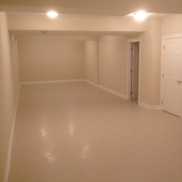
Today is the start of the design and construction of version 2 of the PRR Panhandle Division.

Here is the blank canvas.

IMG_1019IMG_1020

The Prototype - Background & History

This layout is my second attempt to model the 7 miles of the PRR Panhandle that ran through the northern panhandle of West Virginia and Steubenville, OH. The Panhandle was a second mainline of the Pennsylvania Railroad that ran from Pittsburgh to St. Louis.  It existed from 1848 through 1995.  Grif Teller immortalized the double track bridge across the Ohio River in the painting “Crossroads of Commerce” which appeared in the 1953 Pennsylvania Railroad Calendar.  That bridge still stands and the track using it serves Weirton Steel (now Arcelor Mittal) and the brick refractories and businesses on the New Cumberland secondary.  Unfortunately from Weirton Junction through Burgettstown and points east, the track has been pulled up and the right of way has been converted to a hiking / bike trail.

I grew up in Weirton, WV in the 1950s & 1960s. I left in 1978, but still have family and other ties in the area. The PRR double-track bridge at MP 42.11 was always a source of fascination for me, even as a small child going to Steubenville with my parents and grandparents. However, it was not until I saw Teller’s painting (in the late 1990s) that I realized what I wanted to model.


Vital Statistics of the proposed Layout:

  • Size & Shape:  Folded dog bone – 11’ x 41’.  In addition there is a 10' x 6' staging yard behind the eastern backdrop.  Total dimensions are 11’ x 47’ (517 square feet).
  • Track:  Mostly GarGraves with some Curtis sectional curves, Curtis Hi-Rail turnouts, and Ross Custom Switch turnouts.  Mainline curves are O72.
  • Yards:  Weirton Junction, Weirton Steel, Coal Mine Spur, Staging.
  • Command System:  TMCC. Turnouts have Z-Stuff DZ-2500C switch machines and are both TMCC and pushbutton controlled.
  • Wiring & Blocking:  8 power districts will be supplied from 1 centrally located power distribution panel. Bus wiring will be used.
  • Power:  6 Lionel 180 watt PowerHouses and 2 Lionel 135 watt Powerhouses will supply power to districts 1-8. Two (2) K-Line PowerChief 120 transformers will power switch machines, lights, and some AC accessories.  All DC accessories, building lights, traffic signals and street lights get their power from various 3VDC, 5VDC, and 12VDC power supplies.
  • Signals:  Z-Stuff DZ-1060 PRR position signals (9) & MTH PRR signal bridges (2).  The layout is only signaled for travel in the counter-clockwise direction.


Differences between Version 1.0 and Version 2.0

I feel that the increase in size (primarily length) will contribute to a more accurate representation of the area.  Panhandle 1.0 was an ambitious design crippled by limited space.  Panhandle 2.0 is similar in its major design aspects, but the additional space will allow those features to be separated by scenery.  My intention is to avoid crowding layout elements and give a real sense of distance between the features.


Construction Goals:

  • Select a uniform height (50”) that facilitates working underneath comfortably.
  • Avoid grades and take steps to make track as issue-free as possible.
  • Make the fascia, table tops, and legs as attractive as possible; use high quality wood and stain exposed components. Plan for layout skirting.
  • Minimize the use of cookie cutter sub-roadbed.
  • Make aisles wide enough for comfort and provide space for seating at least a dozen people.


Operational Goals:

  • Allow the simultaneous operation of at least 3 trains on the mainline and up to 3 switchers in yards or spurs.
  • Use a signaling system that prevents collisions.
  • Have curves large enough to permit the use of the largest PRR locomotives and scale passenger cars (requires O72).
  • Permit the running of long trains (10-20 hoppers or 8 passenger cars).
  • Allow operating sessions to take place.


Electrical Goals

Panhandle 1.0 (2005-2016) was originally conceived (back in 1997) as a conventional layout (a tip of the hat to Rich Melvin for his help on conventional electrical blocking ).  In 2005, I decided to install TMCC, but was influenced by the arrival of DCS.  After trying a DCS/TMCC combination during construction, I decided TMCC was the direction to pursue.  In 2007, the change was made to solely TMCC.  Home run wiring and light bulbs (as block power indicators) were retained in the design.

For Panhandle 2, the electrical plan divides the layout into 8 blocks or power districts – 4 mainline, 1 separate loop, and 3 yards - with the ability to individually control power to the yards.  The loop and mainline (districts 1-5) and yards (districts 6-8) are all command controlled.  District 1, which is a separate loop for the kids (River Route), will be operable in either command or conventional mode.

  • Eliminate multiple power distribution panels.
  • Simplify and improve labeling for all wires.
  • Make use of 2-color zip-cord where practical.
  • Improve wiring reliability and crimping techniques.


Much more detail to follow, but those are my goals and thinking as I take the first steps down the road.

As always, your thoughts, suggestions, and questions are welcome.

George

Attachments

Images (2)
  • IMG_1019
  • IMG_1020
Last edited by G3750
Original Post

Replies sorted oldest to newest

George,

What a pristine space for your new layout!  Thank you for all the background information to refresh memory and add too what you wrote in the previous version.  Yes I think the additional length of the layout will allow you to do better justice to the original plan!  

Since you have photos of the room, have you taken position of the house yet?  Of course I know you will be busy with moving, getting settled, and a host of other tasks in the near future!

I am looking forward to seeing the new plan and how construction develops!  I hope to be able to see it firsthand since you won't be very far from me.

Mark Boyce posted:

George,

What a pristine space for your new layout!  Thank you for all the background information to refresh memory and add too what you wrote in the previous version.  Yes I think the additional length of the layout will allow you to do better justice to the original plan!  

Since you have photos of the room, have you taken position of the house yet?  Of course I know you will be busy with moving, getting settled, and a host of other tasks in the near future!

I am looking forward to seeing the new plan and how construction develops!  I hope to be able to see it firsthand since you won't be very far from me.

Mark,

I'm up to my *** in alligators, but here's a photo of the house taken on Friday (move-in day).

IMG_1027

And I'll invite you over when we are not totally surrounded and done going crazy.

George

Attachments

Images (1)
  • IMG_1027

G3750, Congratulations to you and your wife for building such a beautiful home and even better a Fantastic Train Room.  The pictures are so good and Your Plan of action sounds so promising...We wish you the best of fun, safety, and Pleasure of building your New Dream Layout....Please keep us updated as to your Progress and ideas.  This will be an Adventure we want to be part of...Thank You. IMG_7901

Attachments

Images (1)
  • IMG_7901

Updated 5/11/2017:

Yesterday, I rechecked the dimensions of the room and discovered that the terrain differs from the map, so to speak. The left half of the room is actually 13'8" wide, not 14'.  At 20'10" from the left wall, it narrows to be only 12'8" wide all the way to the right wall.  So, I am currently tweaking the layout a bit to fit those dimensions while retaining adequate (3' wide) aisle space along the front of the layout.  Fortunately, the general shape of the layout will be preserved.  This will work!

Another change to the track plan involves the addition of a hidden run-around loop in the Weirton Steel area.  This will allow a switcher to pull a load into the mill and then escape.

Updates to the track plan are coming soon.  This unpacking and setting up the house is really getting in the way of working on the layout! 

George

Updated 5/16/2017:

I have rendered, as best I could, the train room and the layout's placement within it.  Yesterday, I took a number of detailed measurements of the room and created a Visio drawing of it.  Then I placed a JPEG of the RR-Track layout on top of it.  It's not perfect, but it should convey the main idea.  Anywhere you see solid white or gray areas are aisles.  I couldn't extend those to fit the odd shape of the areas, so I created blank spots (grayish-blue) and labeled them as aisles as well.  The spaces are actually, in fact, contiguous.  I think we end up with an aisle at the front right of the layout that is minimally 30" (maybe 34") wide.

The leftmost door leads to the workshop. The center door opens to a closet under the stairs. The rightmost door leads to the roughed in powder room / furnace room. The stairs lead up to the main floor.

Train Room4

Your thoughts, suggestions, and questions are always welcome.

George

Attachments

Images (1)
  • Train Room4
Last edited by G3750

George,

Yes I am able to pick out the aisle areas and see that the different colored areas are really one big, long space.  Please refresh my memory from the previous plan.  Are the red spaces pop-up access holes?  As I recall, the area to the right of the large mill is staging for trains and also single engines in the corners.  Are there some areas around the mill that you won't be able to reach easily once the mill is in place, or will it be removable?  It looks to me like your adjusted, previous plan works out nicely in the new, long space.

George,

I think the Panhandle was mostly double track.     Here is a suggestion for the mainlline that would give you more the look of double track.    This is just a schematic, not to scale.    It also gives you more aisle access.    You would turn the towns and industries and put them along the tracks.    Just an idea.

Attachments

Images (1)
  • mceclip0
Mark Boyce posted:

George,

Yes I am able to pick out the aisle areas and see that the different colored areas are really one big, long space.  Please refresh my memory from the previous plan.  Are the red spaces pop-up access holes?  As I recall, the area to the right of the large mill is staging for trains and also single engines in the corners.  Are there some areas around the mill that you won't be able to reach easily once the mill is in place, or will it be removable?  It looks to me like your adjusted, previous plan works out nicely in the new, long space.

Mark,

Yes, the red areas are pop-up access holes, either hatches or hand-only.   The area to the right of the mills (there's a divider there that might be difficult to see) is for staging and engine storage.   I also intend to install some shelving on the walls and / or back of the divider / backdrop in that area.  Not shown in the staging area is the small window near the ceiling that may be used to help vent smoke / heat during operating sessions. 

Not all of the red areas are visible in the diagram; some of them are under the largest mill (Open Hearth, that's 2nd from the bottom of the layout).  My intent is to have all mill spurs within easy reach.  Ideally, I don't want to be lifting large mills in/out of position.  And with a layout height of 4', I can simply roll under there and retrieve / fix what goes astray.

Thank you, I also believe the adjustments are working out as well.  The longer new space does lend itself to the original design pretty well.

George

prrjim posted:

George,

I think the Panhandle was mostly double track.     Here is a suggestion for the mainlline that would give you more the look of double track.    This is just a schematic, not to scale.    It also gives you more aisle access.    You would turn the towns and industries and put them along the tracks.    Just an idea.

Jim,

Thank you so much for taking the time and effort to put this idea in front of me! 

And yes, the Panhandle was double-tracked, 3 tracked, and even 4 tracked in some spots.

With some tweaks, I think the eastern side of the layout already follows your direction.  However, I will take a crack at revising the Steubenville part and see how that plays out vis-a-vis room spacing.

Thanks again!

George

Last edited by G3750

George remember as you get older, crawling under the layout to reach an access hole, or crawling across the top gets less and less appealing..      So getting aisle acess to as much as possible is often works out down the road.     You could build it all 30-36 inches wide and put the tracks in reach almost everywhere.    Put the buildings and scenery toward the back.

Updated 6/5/2017:

We are having some dribbles of progress, little baby-steps towards getting the workshop and train room prepared for bigger things.

First photo is of the major set of shelves in the workshop. I am still finding bins, but we've gotten a lot in place.

DSCN2623

Second photo is of one of the spots in the workshop reserved for a pegboard.  The other pegboard will go on the wall to the right of the door.

DSCN2624

Here's a shot of the pegboard and furring strips awaiting the opportunity for assembly.

DSCN2626

Final shot is of the exhaust fan I found.  It's just above what will become the staging area.

DSCN2625

Like I said, slow progress, but at least it's a start. 

George

Attachments

Images (4)
  • DSCN2623
  • DSCN2624
  • DSCN2626
  • DSCN2625

Updated 6/9/2017:

I've made some progress on the lighting front.  I decided the obvious solution to getting identical lighting in both the workshop and the train room was to (DOH!) do the same lighting fixtures and bulbs.  Instead of going for shop lights in the workshop and track lighting in the train room, I am just doing track lighting everywhere.  I had a very helpful visit from a lighting sales person at the house yesterday.  He knew the products, lighting, and worked hard to understand what I wanted.  Track lighting with 4100K bulbs will give me the flexibility to play around with dispersing light and seeing how the color works in the room.  And it will be less expensive than LED shop lights. 

This is a big step forward and I'm pretty happy about it!   

George

Updated 6/22/2017:

Happy to report some progress:

  • After 45 days, we were able to put the car in the garage! :lol:
  • All major appliances are in and operational!
  • Garage is semi-organized!
  • First pegboard sheet has been installed.

DSCN2639

DSCN2647

One 3' x 8' pegboard sheet will go below this one and another will be installed to the right of it. An access hole will be cut for the electrical panel.

Slow, but steady. I am using 2.5" drywall screws through the drywall into the 2"x4" stud beneath. The pegboard is attached with 1 3/8" drywall screws and fender washers into the furring strips. Yeah, it's overbuilt, but that's my approach after the hard-won lessons of PRR Panhandle 1.0. :lol:

So far, so good.

George

Attachments

Images (2)
  • DSCN2639
  • DSCN2647

George, Looks like you are moving along nicely!  You beat us, after roughly 2100 days in this house, we still can't get the car in the garage.  My wife keeps saying she will go through it all, but I'm not holding my breath.    Pegboard, no not here; my father-in-law put the old kitchen cabinets up all over the walls, and there is no room for pegboard here.  

Yes, you did come back in the nick of time for the Penguins victory!  

Add Reply

Post
×
×
×
×
Link copied to your clipboard.
×
×